
Electronics Fundamentals: Circuits, Devices & Applications
8th Edition
ISBN: 9780135072950
Author: Thomas L. Floyd, David Buchla
Publisher: Prentice Hall
expand_more
expand_more
format_list_bulleted
Videos
Textbook Question
Chapter 17, Problem 19P
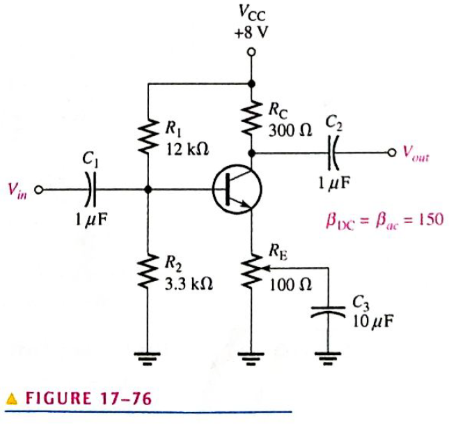
The amplifier in Figure 17-76 has a variable gain control, using a
Expert Solution & Answer
Want to see the full answer?
Check out a sample textbook solution
Students have asked these similar questions
Electrical Engineering
Interference signals from outside of a difference amp circuit can be mitigated by using proper
and
techniques.
A single phase fully controlled bridge converter supplies a load drawing constant
and ripple free load current, if the triggering angle is 30°, the input power factor
will be
The hardware sytem operate under a static dicipline with the following thresholds VIL=1.3V ,VIH=2.4V,VOL=0.6V and VOH=3.8V compute the noise margin and draw the properly labelled noise margin figure for this system
Chapter 17 Solutions
Electronics Fundamentals: Circuits, Devices & Applications
Ch. 17 - In a bipolar transistor, if the base-emitter...Ch. 17 - When a transistor is saturated. an increase in...Ch. 17 - Prob. 3TFQCh. 17 - The power gain of a CC amplifier is the same as...Ch. 17 - A class B amplifier is more efficient than a class...Ch. 17 - A JFET is always operated with the gate-source...Ch. 17 - Prob. 7TFQCh. 17 - The transconductance of a FET is the ratio of ac...Ch. 17 - Prob. 9TFQCh. 17 - The input to a feedback oscillator is only the...
Ch. 17 - The n-type regions in an npn bipolar junction...Ch. 17 - The n-region in a pnp transistor is the base...Ch. 17 - Prob. 3STCh. 17 - Prob. 4STCh. 17 - Prob. 5STCh. 17 - Alpha () is the ratio of collector current to...Ch. 17 - If the beta of a certain transistor operating in...Ch. 17 - If the base current of a transistor operating in...Ch. 17 - Prob. 9STCh. 17 - When the gate-to-source voltage of an n-channel...Ch. 17 - When a negative gate-to-source voltage is applied...Ch. 17 - Prob. 12STCh. 17 - If the capacitor from emitter to ground in a CE...Ch. 17 - When the collector resistor in a CE amplifier is...Ch. 17 - The input resistance of a CE amplifier is affected...Ch. 17 - The output signal of a CE amplifier is always in...Ch. 17 - The output signal of a common-collector amplifier...Ch. 17 - The largest theoretical voltage gain obtainable...Ch. 17 - In a class A amplifier, the output signal is...Ch. 17 - A class A amplifier conducts for 90 of input cycle...Ch. 17 - Prob. 21STCh. 17 - Feedback oscillators operate on the principle of...Ch. 17 - What is the value of IC for IE=5.34mA and IB=475A?Ch. 17 - Prob. 2PCh. 17 - Prob. 3PCh. 17 - In a certain transistor circuit, the base current...Ch. 17 - Find IB,IE, and in Figure 17-70 given that DC=0.98...Ch. 17 - The transistor in Figure 17-70 is replaced with...Ch. 17 - Prob. 7PCh. 17 - Prob. 8PCh. 17 - Determine IB,IC, and VC in Figure 17-72.Ch. 17 - For the circuit in Figure 17-73, find VB,VE,IE,IC,...Ch. 17 - In Figure 17-73, what is VCE? What are the Q-point...Ch. 17 - A transistor amplifier has a voltage gain of 50....Ch. 17 - To achieve an output of 10 V with an input of300...Ch. 17 - A 50 mV signal is applied to the base of a...Ch. 17 - Determine the voltage gain for Figure 17-74.Ch. 17 - Determine each of the dc voltages, VB,VC, and VE,...Ch. 17 - Determine the following dc values for the...Ch. 17 - Determine the following ac values for the...Ch. 17 - The amplifier in Figure 17-76 has a variable gain...Ch. 17 - If a load resistance of 600 is placed on the...Ch. 17 - Determine the voltage gain for the...Ch. 17 - What is the total input resistance in Figure...Ch. 17 - A load resistance is capacitively coupled in the...Ch. 17 - Prob. 24PCh. 17 - Determine the maximum peak output voltage and peak...Ch. 17 - The efficiency of a certain class B push-pull...Ch. 17 - Prob. 27PCh. 17 - The transistor in Figure 17-80 has a DC of 150....Ch. 17 - The VGS of ap-channel JFET is increased from 1 V...Ch. 17 - Why must the gate-to-source voltage of an...Ch. 17 - Draw the schematic symbols for n-channel and...Ch. 17 - Explain why both types of MOSFETs have an...Ch. 17 - In what mode is an n-channel D-MOSFET operating...Ch. 17 - A certain E-MOSFET has a VGS(th)=3V. What is the...Ch. 17 - For each circuit in Figure 17-81, determine VDS...Ch. 17 - Prob. 36PCh. 17 - Each E-MOSFET in Figure 17-83 has a VGS(th) of +5...Ch. 17 - Prob. 38PCh. 17 - Find the gain of each amplifier in Figure 17-85.Ch. 17 - Determine the gain of each amplifier in Figure...Ch. 17 - If the voltage gain of the amplifier portion of a...Ch. 17 - Generally describe the change required to the...Ch. 17 - Prob. 43PCh. 17 - Prob. 44PCh. 17 - Prob. 47PCh. 17 - Prob. 48PCh. 17 - Prob. 49PCh. 17 - Prob. 50PCh. 17 - Prob. 51PCh. 17 - Prob. 52PCh. 17 - Open file P17-53. Determine if the circuit is...
Knowledge Booster


Learn more about
Need a deep-dive on the concept behind this application? Look no further. Learn more about this topic, electrical-engineering and related others by exploring similar questions and additional content below.Similar questions
- What is the output peak voltage during the positive alternation of the input signal for the circuit shown below? •.. Vị 1+20V + Si vi 1.Ok Vo 5 V -20V A) 24.3 V B - 5 V - 24.3 V D) - 4.3 Varrow_forwardThe upper cutoff frequency of this amplifoer is 22KHz. The output at that frequency is 6.71V p-p. What is the output voltage of 220kHz.arrow_forwardWhat is the noise figure when the input signal and the noise values are 200 and 20uW and the output signal and noise values are 2 and 0.8 W?arrow_forward
- please write Details about Verification of series RL series circuitarrow_forwardA circuit consist of two cascaded opamp amplifiers, If the gain of first stage is 6.7 and the gain of the second stage is 3. Then the total voltage gain A, isarrow_forward4. Although current is blocked in reverse bias, (a) there is some current due to majority carriers (b) there is a very small current due to minority carriers (c) there is an avalanche currentarrow_forward
- COMMON EMITTER What will be the effect on the output voltage if we change the value of the following components? a. collector resistor, Rc b. bypass capacitor c. no bypass capacitorarrow_forwardSingle phase full wave controlled converter circuit is powered by a single phase source. When the trigger angle is 0 °, the DC output voltage taken from the output of the converter circuit is 300V. If the trigger angle is 60 °, what is the value of the DC output voltage to be obtained at the output? i have 1 hourearrow_forwardQ2. Consider the following RISC-V loop: (i) (ii) (iii) (iv) (iv) (v) (vi) (vii) LOOP: beq x6, addi x6, x6, -1 add x11, x11, x5 addi x5, x5, 2 slli x7, x5, 1 beq x0, x0, LOOP beq x11, x0, DONE 2 | Page Assume that the register x6 is initialized to the value 5, x5 and x7 to the value 0, and x11 to the last digit of your student ID. All these initializations are performed using RISC-V instructions. Fill out the table below. Final value of x5 at the end of execution Final value of x7 at the end of execution Total number of instructions executed DONE: add x12, x11, x19 microarchitecture x0, DONE Number of cycles needed to execute these instructions in a single cycle microarchitecture Number of cycles needed to execute these instructions in a multi-cyclearrow_forward
- if you design differentiator to differentiate input signal varies in frequency between 1 KHz and 20 KHz then find. Cutoff frequency=.......... 01000 O2000 03000 O4000arrow_forwardpower electronics 5- For a DC-DC Converter; The input voltage of the circuit is 12 V, the switching frequency is 1 KHz, the output voltage is 48 V and the output power is 24W. In which options are the smallest coil value required for the coil current to be continuous and the smallest capacitance value that will ensure that the output voltage ratio is less than 62% for this value ? c means The question cannot be solved due to lack of data.arrow_forwardA buck regulator has Vref = 2.21 V, R, = 1 kn, and Rz = 5 kn. What is the output voltage?arrow_forward
arrow_back_ios
SEE MORE QUESTIONS
arrow_forward_ios
Recommended textbooks for you
 Introductory Circuit Analysis (13th Edition)Electrical EngineeringISBN:9780133923605Author:Robert L. BoylestadPublisher:PEARSON
 Delmar's Standard Textbook Of ElectricityElectrical EngineeringISBN:9781337900348Author:Stephen L. HermanPublisher:Cengage Learning
 Programmable Logic ControllersElectrical EngineeringISBN:9780073373843Author:Frank D. PetruzellaPublisher:McGraw-Hill Education
 Fundamentals of Electric CircuitsElectrical EngineeringISBN:9780078028229Author:Charles K Alexander, Matthew SadikuPublisher:McGraw-Hill Education
 Electric Circuits. (11th Edition)Electrical EngineeringISBN:9780134746968Author:James W. Nilsson, Susan RiedelPublisher:PEARSON
 Engineering ElectromagneticsElectrical EngineeringISBN:9780078028151Author:Hayt, William H. (william Hart), Jr, BUCK, John A.Publisher:Mcgraw-hill Education,
Introductory Circuit Analysis (13th Edition)
Electrical Engineering
ISBN:9780133923605
Author:Robert L. Boylestad
Publisher:PEARSON
Delmar's Standard Textbook Of Electricity
Electrical Engineering
ISBN:9781337900348
Author:Stephen L. Herman
Publisher:Cengage Learning
Programmable Logic Controllers
Electrical Engineering
ISBN:9780073373843
Author:Frank D. Petruzella
Publisher:McGraw-Hill Education
Fundamentals of Electric Circuits
Electrical Engineering
ISBN:9780078028229
Author:Charles K Alexander, Matthew Sadiku
Publisher:McGraw-Hill Education
Electric Circuits. (11th Edition)
Electrical Engineering
ISBN:9780134746968
Author:James W. Nilsson, Susan Riedel
Publisher:PEARSON
Engineering Electromagnetics
Electrical Engineering
ISBN:9780078028151
Author:Hayt, William H. (william Hart), Jr, BUCK, John A.
Publisher:Mcgraw-hill Education,
Boost Converters and Buck Converters: Power Electronics; Author: Physics Videos by Eugene Khutoryansky;https://www.youtube.com/watch?v=vwJYIorz_Aw;License: Standard Youtube License