
Electronics Fundamentals: Circuits, Devices & Applications
8th Edition
ISBN: 9780135072950
Author: Thomas L. Floyd, David Buchla
Publisher: Prentice Hall
expand_more
expand_more
format_list_bulleted
Concept explainers
Videos
Textbook Question
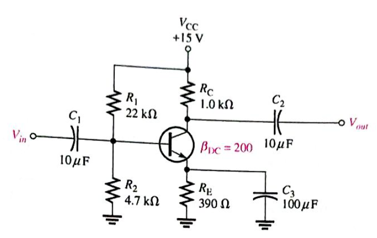
Chapter 17, Problem 16P
Determine each of the dc voltages,
Expert Solution & Answer
Want to see the full answer?
Check out a sample textbook solution
Students have asked these similar questions
Hw MANY MODES, LOOP, MEH IN
THE FIEURE
Calculate the value of RC in ohms.
at VCC=17 V, IB=27 uA, and VC=7V and B=74
Calculate circuit values below. How does the total circuit impedence change as the frequency increases from 500 HZ to 50 Khz? How does the total current change as those frequencies increase?
Chapter 17 Solutions
Electronics Fundamentals: Circuits, Devices & Applications
Ch. 17 - In a bipolar transistor, if the base-emitter...Ch. 17 - When a transistor is saturated. an increase in...Ch. 17 - Prob. 3TFQCh. 17 - The power gain of a CC amplifier is the same as...Ch. 17 - A class B amplifier is more efficient than a class...Ch. 17 - A JFET is always operated with the gate-source...Ch. 17 - Prob. 7TFQCh. 17 - The transconductance of a FET is the ratio of ac...Ch. 17 - Prob. 9TFQCh. 17 - The input to a feedback oscillator is only the...
Ch. 17 - The n-type regions in an npn bipolar junction...Ch. 17 - The n-region in a pnp transistor is the base...Ch. 17 - Prob. 3STCh. 17 - Prob. 4STCh. 17 - Prob. 5STCh. 17 - Alpha () is the ratio of collector current to...Ch. 17 - If the beta of a certain transistor operating in...Ch. 17 - If the base current of a transistor operating in...Ch. 17 - Prob. 9STCh. 17 - When the gate-to-source voltage of an n-channel...Ch. 17 - When a negative gate-to-source voltage is applied...Ch. 17 - Prob. 12STCh. 17 - If the capacitor from emitter to ground in a CE...Ch. 17 - When the collector resistor in a CE amplifier is...Ch. 17 - The input resistance of a CE amplifier is affected...Ch. 17 - The output signal of a CE amplifier is always in...Ch. 17 - The output signal of a common-collector amplifier...Ch. 17 - The largest theoretical voltage gain obtainable...Ch. 17 - In a class A amplifier, the output signal is...Ch. 17 - A class A amplifier conducts for 90 of input cycle...Ch. 17 - Prob. 21STCh. 17 - Feedback oscillators operate on the principle of...Ch. 17 - What is the value of IC for IE=5.34mA and IB=475A?Ch. 17 - Prob. 2PCh. 17 - Prob. 3PCh. 17 - In a certain transistor circuit, the base current...Ch. 17 - Find IB,IE, and in Figure 17-70 given that DC=0.98...Ch. 17 - The transistor in Figure 17-70 is replaced with...Ch. 17 - Prob. 7PCh. 17 - Prob. 8PCh. 17 - Determine IB,IC, and VC in Figure 17-72.Ch. 17 - For the circuit in Figure 17-73, find VB,VE,IE,IC,...Ch. 17 - In Figure 17-73, what is VCE? What are the Q-point...Ch. 17 - A transistor amplifier has a voltage gain of 50....Ch. 17 - To achieve an output of 10 V with an input of300...Ch. 17 - A 50 mV signal is applied to the base of a...Ch. 17 - Determine the voltage gain for Figure 17-74.Ch. 17 - Determine each of the dc voltages, VB,VC, and VE,...Ch. 17 - Determine the following dc values for the...Ch. 17 - Determine the following ac values for the...Ch. 17 - The amplifier in Figure 17-76 has a variable gain...Ch. 17 - If a load resistance of 600 is placed on the...Ch. 17 - Determine the voltage gain for the...Ch. 17 - What is the total input resistance in Figure...Ch. 17 - A load resistance is capacitively coupled in the...Ch. 17 - Prob. 24PCh. 17 - Determine the maximum peak output voltage and peak...Ch. 17 - The efficiency of a certain class B push-pull...Ch. 17 - Prob. 27PCh. 17 - The transistor in Figure 17-80 has a DC of 150....Ch. 17 - The VGS of ap-channel JFET is increased from 1 V...Ch. 17 - Why must the gate-to-source voltage of an...Ch. 17 - Draw the schematic symbols for n-channel and...Ch. 17 - Explain why both types of MOSFETs have an...Ch. 17 - In what mode is an n-channel D-MOSFET operating...Ch. 17 - A certain E-MOSFET has a VGS(th)=3V. What is the...Ch. 17 - For each circuit in Figure 17-81, determine VDS...Ch. 17 - Prob. 36PCh. 17 - Each E-MOSFET in Figure 17-83 has a VGS(th) of +5...Ch. 17 - Prob. 38PCh. 17 - Find the gain of each amplifier in Figure 17-85.Ch. 17 - Determine the gain of each amplifier in Figure...Ch. 17 - If the voltage gain of the amplifier portion of a...Ch. 17 - Generally describe the change required to the...Ch. 17 - Prob. 43PCh. 17 - Prob. 44PCh. 17 - Prob. 47PCh. 17 - Prob. 48PCh. 17 - Prob. 49PCh. 17 - Prob. 50PCh. 17 - Prob. 51PCh. 17 - Prob. 52PCh. 17 - Open file P17-53. Determine if the circuit is...
Knowledge Booster


Learn more about
Need a deep-dive on the concept behind this application? Look no further. Learn more about this topic, electrical-engineering and related others by exploring similar questions and additional content below.Similar questions
- the following waveform is the inductor current of the buck converter, the ripple current is equal to Q7) the following waveform is the inductor current of the buck converter, the ripple current is equal to Inductor current 35 30- 25- 20- Lead voltage Oa) 14A b) 15A c) 16A d) 17Aarrow_forward1.Using the simulator of your choice simulate and screenshot the output voltage wave form for each circuit. +50 V R +5 V Vin Vout R- 47 0 3.3 kN Vin V out -50 V -5 V B Aarrow_forwardRc does not look like a standard resistor value? and what about choosing value for Re, it has to be standard value as wellarrow_forward
- What is the voltage between nodes A and B in each circuit in Figure 12–73?arrow_forwardWhen in forward biased, what have you noticed when you change the source voltage from 0V to +20V? When in reverse biased, what have you noticed when changing the source voltage from 0 V to -15V?arrow_forward& 7 *00 8 O - 2. A series voltage regulator with constant-current limiting is shown in Figure 17-47. Determine the value of R4 if the load current is to be limited to a maximum value of 250 mA. What power rating must R4 have? VINO- R₁ 12 ΚΩ wwwm 3 V wwwwwww täköhtüchtüküklükzülükcertitza 2₁ Q₂ RA www -O VOUT R₂ 10 ΚΩ ww R3 4.7 ΚΩarrow_forward
- Very urgent. Draw the waveforms of the voltage at the load (RL) end, the voltage at the R end, the voltage at the L end and the current 1 when the switch K is turned to position 2 after a long enough time.arrow_forwardD4 D1 RL2ル 1.2K VsN D3 Y D2 9V sin(27 50 t) + ;arrow_forwardWhat are RC AND RB resistors?arrow_forward
- The input voltage to chopper circuit with a switching frequency of 100 Hz and TOn time as 2.0 ms is 10 V. The average DC output is: O 4V O 2V O 6V O 8Varrow_forwardThe value of Ai is . . NOTE: When the output is taken from the collector terminal of the transistor as shown in Figure O 85.613 O 78.613 65.613 81.613 89.613 71.613 The value of Zo is .. . ohm. . * 12.897 8.897 6.897 4.897 9.897 O 3.897 The value of Av is .. NOTE: When the output is taken from the collector terminal of the transistor as shown in Figure -17.597 -14.597 -19.597 -21.597 -8.597 -11.597 O O O O O O O O O Oarrow_forward4. A 10 resistance in parallel with a 20 resistance provides a combined equivalent resistance of a) 30 b) 192 c) 20 d) 2/30arrow_forward
arrow_back_ios
SEE MORE QUESTIONS
arrow_forward_ios
Recommended textbooks for you
 Delmar's Standard Textbook Of ElectricityElectrical EngineeringISBN:9781337900348Author:Stephen L. HermanPublisher:Cengage Learning
 Electricity for Refrigeration, Heating, and Air C...Mechanical EngineeringISBN:9781337399128Author:Russell E. SmithPublisher:Cengage Learning
Delmar's Standard Textbook Of Electricity
Electrical Engineering
ISBN:9781337900348
Author:Stephen L. Herman
Publisher:Cengage Learning
Electricity for Refrigeration, Heating, and Air C...
Mechanical Engineering
ISBN:9781337399128
Author:Russell E. Smith
Publisher:Cengage Learning
Maxwell's Equations Visualized (Divergence & Curl); Author: The Science Asylum;https://www.youtube.com/watch?v=UzW_jAJzlgI;License: Standard Youtube License