
Mechanics of Materials (10th Edition)
10th Edition
ISBN: 9780134319650
Author: Russell C. Hibbeler
Publisher: PEARSON
expand_more
expand_more
format_list_bulleted
Videos
Textbook Question
Chapter 1.7, Problem 1.95P
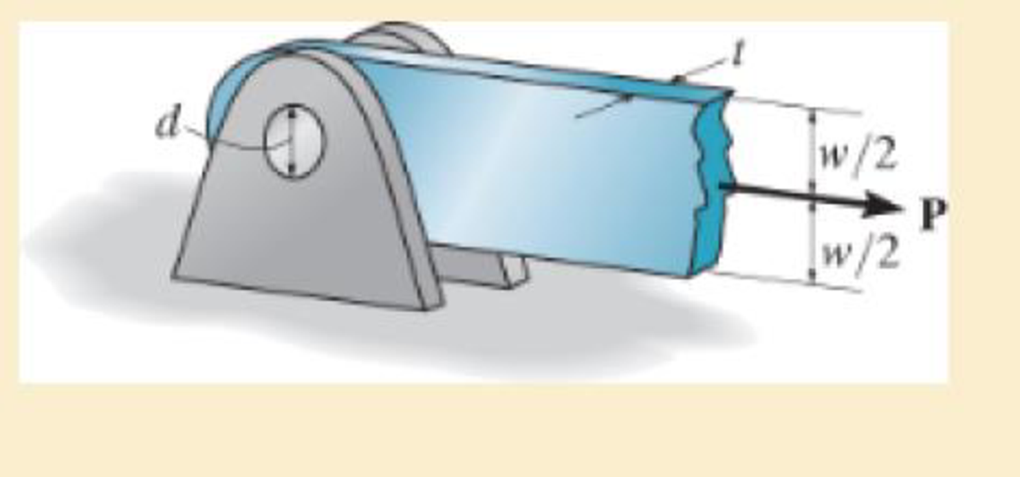
If the allowable tensile stress for the bar is (σt)allow = 21 ksi, and the allowable shear stress for the pin is τallow = 12 ksi, determine the diameter of the pin so that the load P will be a maximum. What is this load? Assume the hole in the bar has the same diameter d as the pin. Take
Expert Solution & Answer
Want to see the full answer?
Check out a sample textbook solution
Students have asked these similar questions
If the allowable tensile stress for the bar is 1st2allow = 21 ksi, and the allowable shear stress for the pin is tallow = 12 ksi, determine the diameter of the pin so that the load P will be a maximum. What is this load? Assumethe hole in the bar has the same diameter d as the pin. Take t = 1 4 in. and w = 2 in.
5. The hanger is supported using the rectangular pin.
Determine the magnitude of the allowable suspended load
P if the allowable bearing stress is b,allow = 220 MPa, the
allowable tensile stress is at,allow = 150 MPa, and the
allowable shear stress is Tallow = 130 MPa. Take t = 6 mm,
a = 5 mm and b = 25 mm.
75 mm
37.5 mm
20 mm
10 mm
37.5 mm
the right-angle bar is supported by a pin at B and a roller at C. what is the maximum safe value of the load P that can be applied if the shear stress in the pin is limited to 20000 psi? the 3/4 in diameter pin is in double shear
Chapter 1 Solutions
Mechanics of Materials (10th Edition)
Ch. 1.2 - In each case, explain how to find the resultant...Ch. 1.2 - Determine the resultant internal normal force,...Ch. 1.2 - Determine the resultant internal normal force,...Ch. 1.2 - Determine the resultant internal normal force,...Ch. 1.2 - Determine the resultant internal normal force,...Ch. 1.2 - Determine the resultant internal normal force,...Ch. 1.2 - Determine the resultant internal normal force,...Ch. 1.2 - The shaft is supported by a smooth thrust bearing...Ch. 1.2 - Determine the resultant internal normal and shear...Ch. 1.2 - Determine the resultant internal loadings acting...
Ch. 1.2 - The shaft is supported by a smooth thrust bearing...Ch. 1.2 - Determine the resultant internal loadings acting...Ch. 1.2 - Determine the resultant internal loadings on the...Ch. 1.2 - Determine the resultant internal loadings at cross...Ch. 1.2 - The beam supports the distributed load shown....Ch. 1.2 - The beam supports the distributed load shown....Ch. 1.2 - The boom DF of the jib crane and the column DE...Ch. 1.2 - Determine the resultant internal loadings acting...Ch. 1.2 - Determine the resultant internal loadings acting...Ch. 1.2 - The blade of the hacksaw is subjected to a...Ch. 1.2 - The blade of the hacksaw is subjected to a...Ch. 1.2 - The beam supports the triangular distributed load...Ch. 1.2 - The beam supports the distributed load shown....Ch. 1.2 - The shaft is supported at its ends by two bearings...Ch. 1.2 - The shaft is supported at its ends by two bearings...Ch. 1.2 - The hand crank that is used in a press has the...Ch. 1.2 - Determine the resultant internal loadings acting...Ch. 1.2 - Determine the resultant internal loadings acting...Ch. 1.2 - The metal stud punch is subjected to a force of...Ch. 1.2 - Determine the resultant internal loadings acting...Ch. 1.2 - Determine the resultant internal loadings acting...Ch. 1.2 - Determine the resultant internal loadings acting...Ch. 1.2 - Determine the resultant internal loadings acting...Ch. 1.2 - The pipe has a mass of 12 kg/m. If it is fixed to...Ch. 1.2 - If the drill bit jams when the brace is subjected...Ch. 1.2 - The curved rod AD of radius r has a weight per...Ch. 1.2 - A differential element taken from a curved bar is...Ch. 1.5 - In each case, determine the largest internal shear...Ch. 1.5 - Determine the largest internal normal force in the...Ch. 1.5 - Determine the internal normal force at section A...Ch. 1.5 - The lever is held to the fixed shaft using the pin...Ch. 1.5 - The single-V butt joint transmits the force of 5...Ch. 1.5 - The uniform beam is supported by two rods AB and...Ch. 1.5 - Determine the average normal stress on the cross...Ch. 1.5 - Determine the average normal stress on the cross...Ch. 1.5 - If the 600-kN force acts through the centroid of...Ch. 1.5 - Determine the average normal stress at points A,...Ch. 1.5 - Determine the average normal stress in rod AB if...Ch. 1.5 - The supporting wheel on a scaffold is held in...Ch. 1.5 - Determine the largest intensity w of the uniform...Ch. 1.5 - The bar has a cross-sectional area A and is...Ch. 1.5 - The small block has a thickness of 0.5 in. If the...Ch. 1.5 - If the material fails when the average normal...Ch. 1.5 - If the block is subjected to a centrally applied...Ch. 1.5 - The plate has a width of 0.5 m. If the stress...Ch. 1.5 - The board is subjected to a tensile force of 200...Ch. 1.5 - The boom has a uniform weight of 600 lb and is...Ch. 1.5 - Determine the average normal stress in each of the...Ch. 1.5 - If the average normal stress in each of the...Ch. 1.5 - Determine the maximum average shear stress in pin...Ch. 1.5 - If P=5 kN, determine the average shear stress in...Ch. 1.5 - Determine the maximum magnitude P of the loads the...Ch. 1.5 - The column is made of concrete having a density of...Ch. 1.5 - The beam is supported by two rods AB and CD that...Ch. 1.5 - The beam is supported by two rods AB and CD that...Ch. 1.5 - If P = 15 kN, determine the average shear stress...Ch. 1.5 - The railcar docklight is supported by the...Ch. 1.5 - The plastic block is subjected to an axial...Ch. 1.5 - The two steel members are joined together using a...Ch. 1.5 - The bar has a cross-sectional area of 400(106) m2....Ch. 1.5 - The bar has a cross-sectional area of 400(106) m2....Ch. 1.5 - The two members used in the construction of an...Ch. 1.5 - The 2-Mg concrete pipe has a center of mass at...Ch. 1.5 - The 2-Mg concrete pipe has a center of mass at...Ch. 1.5 - The pier is made of material having a specific...Ch. 1.5 - Rods AB and BC have diameters of 4 mm and 6 mm,...Ch. 1.5 - The uniform bar, having a cross-sectional area of...Ch. 1.5 - The bar has a cross-sectional area of 400(106) m2....Ch. 1.5 - The bar has a cross-sectional area of 400(106) m2....Ch. 1.5 - The prismatic bar has a cross-sectional area A. If...Ch. 1.5 - The prismatic bar has a cross-sectional area A. If...Ch. 1.5 - The bars of the truss each have a cross-sectional...Ch. 1.5 - The bars of the truss each have a cross-sectional...Ch. 1.5 - Determine the largest load P that can be applied...Ch. 1.5 - Determine the greatest constant angular velocity ...Ch. 1.5 - The radius of the pedestal is defined by r =...Ch. 1.7 - Rods AC and BC are used to suspend the 200-kg...Ch. 1.7 - If it is subjected to double shear, determine the...Ch. 1.7 - Determine the maximum average shear stress...Ch. 1.7 - If each of the three nails has a diameter of 4 mm...Ch. 1.7 - The strut is glued to the horizontal member at...Ch. 1.7 - Determine the maximum average shear stress...Ch. 1.7 - If the eyebolt is made of a material having a...Ch. 1.7 - If the bar assembly is made of a material having a...Ch. 1.7 - Determine the maximum force P that can be applied...Ch. 1.7 - The pin is made of a material having a failure...Ch. 1.7 - If the bolt head and the supporting bracket are...Ch. 1.7 - Six nails are used to hold the hanger at A against...Ch. 1.7 - If A and B are both made of wood and are 38 in....Ch. 1.7 - Prob. 1.70PCh. 1.7 - The connection is made using a bolt and nut and...Ch. 1.7 - The tension member is fastened together using two...Ch. 1.7 - The steel swivel bushing in the elevator control...Ch. 1.7 - The spring mechanism is used as a shock absorber...Ch. 1.7 - Determine the size of square bearing plates A and...Ch. 1.7 - Determine the maximum load P that can be applied...Ch. 1.7 - Determine the required diameter of the pins at A...Ch. 1.7 - If the allowable tensile stress for wires AB and...Ch. 1.7 - If the allowable tensile stress for wires AB and...Ch. 1.7 - The cotter is used to hold the two rods together....Ch. 1.7 - Determine the required diameter of the pins at A...Ch. 1.7 - The steel pipe is supported on the circular base...Ch. 1.7 - The boom is supported by the winch cable that has...Ch. 1.7 - The boom is supported by the winch cable that has...Ch. 1.7 - The assembly consists of three disks A, B, and C...Ch. 1.7 - The two aluminum rods support the vertical force...Ch. 1.7 - The two aluminum rods AB and AC have diameters of...Ch. 1.7 - Determine the required minimum thickness t of...Ch. 1.7 - Determine the maximum allowable load P that can be...Ch. 1.7 - The compound wooden beam is connected together by...Ch. 1.7 - The hanger is supported using the rectangular pin....Ch. 1.7 - The hanger is supported using the rectangular pin....Ch. 1.7 - The rods AB and CD are made of steel. Determine...Ch. 1.7 - The aluminum bracket A is used to support the...Ch. 1.7 - If the allowable tensile stress for the bar is...Ch. 1.7 - The bar is connected to the support using a pin...Ch. 1 - The beam AB is pin supported at A and supported by...Ch. 1 - The long bolt passes through the 30-mm-thick...Ch. 1 - Determine the required thickness of member BC to...Ch. 1 - The circular punch B exerts a force of 2 kN on the...Ch. 1 - Determine the average punching shear stress the...Ch. 1 - The 150 mm by 150 mm block of aluminum supports a...Ch. 1 - The yoke-and-rod connection is subjected to a...Ch. 1 - The cable has a specific weight (weight/volume)...
Knowledge Booster


Learn more about
Need a deep-dive on the concept behind this application? Look no further. Learn more about this topic, mechanical-engineering and related others by exploring similar questions and additional content below.Similar questions
- I Reviev Part A If the allowable tensile stress for the bar is (0t)allow = 22.6 ksi, and the allowable shear stress for the pin is Tallow = 12.2 ksi. Assume the hole in the bar has the same diameter d as the pin. Take t = 1/4 in. and w = 2 in. (Figure 1) Determine the diameter of the pin so that the load P will be a maximum. Express your answer to three significant figures and include appropriate units. HÀ ? d = Value Units Submit Request Answer Part B What is this maximum value for P? Express your answer to three significant figures and include appropriate units. Figure 1 of 1 HA ? w/2 P = Value Units w/2 Submit Request Answerarrow_forwardThe bar is connected to the support using a pin having a diameter of d =lin. If the allowable tensile stress for the bar is (o,)low = 20ksi , and the allowable bearing stress between the pin and the bar is (0,)allow = 30ksi , determine the dimension w and t so that the gross area of the cross section is wt = 2in² and the load P is a maximum. What is this maximum load? Assume the hole in the bar has the same diameter as the pin. (Hint: Use the prjjected area whenj calculating the bearing stress.) t d w/2 w/2arrow_forwardA 75 mm diameter compound bar is constructed by shrinking a circular brass bush onto the outside of a 50 mm diameter solid steel rod. If the compound bar is then subjected to an axial compressive load of 160 kN determine the load carried by the steel rod and the brass bush and the compressive stress set up in each material. For steel, E = 210 GN/m2; for brass, £ = 100 GN/m2arrow_forward
- 3 m Load D 2 m+ 3 m The member AC is made from an aluminium alloy and has a rectangular cross section of 100mm x 10mm. Calculate the stress in member AC if a load of 57.4 kN is applied at point D.arrow_forwardThe lap joint shown is fastened by 4 rivets of ¾ in. diameter. Find the maximum load P that can be applied if the working stress are 14000 psi for shear in the rivet and 18000 psi for bearing in the plate. Assume that the applied load is distributed evenly in the 4 rivets. The plate is 7/8 in. thick and 4 in wide.arrow_forwardThree metal rods are firmly attached to the walls and the middle rigid plate. Rod AB is made from stainless steel and rods CD and EF are made from 2014-T6 aluminum. If a balanced load is applied to the rigid plate, determine what the stresses are in the rods. Follow the sign convention that tensile stress is positive and compressive stress is negative. The parameter values are listed in the table above the figure. A parameter value units 470 mm 400 mm 40 mm 30 mm 30 KN cc 080 BY NO SA 2021 Cathy Zupke L₁ L2 d₁ d₂ P 4₁ B C E The stress in AB σAB= The stress in CD and EF: OCD = EF= d₂ L₂ MPa D F MPaarrow_forward
- Rods AB and BC each have a diameter of 5 mm. If the load of P = 1.5 kN is applied to the ring, determine the average normal stress in each rod if 0 = 50°. B Figure Q1arrow_forwardfind the allowable safe load p if the stresses in the bar are the following : ab=50ksi bc=60 ksi cd= 70 ksiarrow_forward2. The bar AC is supported by a pin at A and a cable that runs from B to E around the frictionless pully at D. If the allowable tensile stress oallow = 5.2 ksi for the cable, determine the required minimum diameter (inch) of the cable. The cylinder (connected at C) weighs 890 lb. Neglect weight and thickness of the bar AC. D 4 3 A C 5 ft 5 ft -4 ft 890 lbarrow_forward
- The 10-mm-diameter steel bolt is surrounded by a bronze sleeve in (Figure 1). The outer diameter of this sleeve is 20 mm, and its inner diameter is 10 mm. If the yield stress for the steel is (σY)st=680MPa, and for the bronze (σY)br=490MPa, determine the magnitude of the largest elastic load P that can be applied to the assembly. Est=200GPa, Ebr=100GPa. Express your answer to three significant figures and include appropriate units.arrow_forwardIf the allowable tensile stress for wires AB and AC is sallow = 200 MPa, determine the required diameter of each wire if the applied load is P = 6 kN.arrow_forwardDetermine the load that can be applied at the end of the rigid bar if the stressin either spring shown in the figure shall not exceed 200MPa. Present detailed drawings/FBD’s illustrating your solution.arrow_forward
arrow_back_ios
SEE MORE QUESTIONS
arrow_forward_ios
Recommended textbooks for you
 Elements Of ElectromagneticsMechanical EngineeringISBN:9780190698614Author:Sadiku, Matthew N. O.Publisher:Oxford University Press
 Mechanics of Materials (10th Edition)Mechanical EngineeringISBN:9780134319650Author:Russell C. HibbelerPublisher:PEARSON
 Thermodynamics: An Engineering ApproachMechanical EngineeringISBN:9781259822674Author:Yunus A. Cengel Dr., Michael A. BolesPublisher:McGraw-Hill Education
 Control Systems EngineeringMechanical EngineeringISBN:9781118170519Author:Norman S. NisePublisher:WILEY
 Mechanics of Materials (MindTap Course List)Mechanical EngineeringISBN:9781337093347Author:Barry J. Goodno, James M. GerePublisher:Cengage Learning
 Engineering Mechanics: StaticsMechanical EngineeringISBN:9781118807330Author:James L. Meriam, L. G. Kraige, J. N. BoltonPublisher:WILEY
Elements Of Electromagnetics
Mechanical Engineering
ISBN:9780190698614
Author:Sadiku, Matthew N. O.
Publisher:Oxford University Press
Mechanics of Materials (10th Edition)
Mechanical Engineering
ISBN:9780134319650
Author:Russell C. Hibbeler
Publisher:PEARSON
Thermodynamics: An Engineering Approach
Mechanical Engineering
ISBN:9781259822674
Author:Yunus A. Cengel Dr., Michael A. Boles
Publisher:McGraw-Hill Education
Control Systems Engineering
Mechanical Engineering
ISBN:9781118170519
Author:Norman S. Nise
Publisher:WILEY
Mechanics of Materials (MindTap Course List)
Mechanical Engineering
ISBN:9781337093347
Author:Barry J. Goodno, James M. Gere
Publisher:Cengage Learning
Engineering Mechanics: Statics
Mechanical Engineering
ISBN:9781118807330
Author:James L. Meriam, L. G. Kraige, J. N. Bolton
Publisher:WILEY
An Introduction to Stress and Strain; Author: The Efficient Engineer;https://www.youtube.com/watch?v=aQf6Q8t1FQE;License: Standard YouTube License, CC-BY