
Mechanics of Materials (10th Edition)
10th Edition
ISBN: 9780134319650
Author: Russell C. Hibbeler
Publisher: PEARSON
expand_more
expand_more
format_list_bulleted
Concept explainers
Videos
Textbook Question
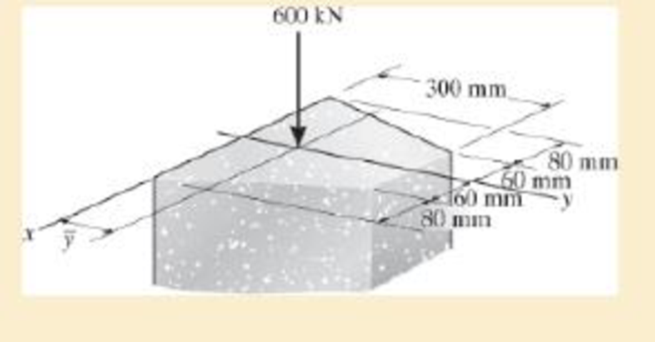
Chapter 1.5, Problem 1.10FP
If the 600-kN force acts through the centroid of the cross section, determine the location ȳ of the centroid and the average normal stress on the cross section. Also, sketch the normal stress distribution over the cross section.
Expert Solution & Answer

Trending nowThis is a popular solution!

Students have asked these similar questions
-6-
8 من 8
Mechanical vibration
HW-prob-1
lecture 8 By: Lecturer Mohammed O. attea
The 8-lb body is released from rest a distance xo
to the right of the equilibrium position.
Determine the displacement x as a function of time t,
where t = 0 is the time of release.
c=2.5 lb-sec/ft
wwwww
k-3 lb/in.
8 lb
Prob. -2
Find the value of (c) if the system is critically
damping.
Prob-3
Find Meq and Ceq at point B, Drive eq. of
motion for the system below.
Ш
H
-7~
+
目
T T & T
тт
+
Q For the following plan of building foundation, Determine
immediate settlement at points (A) and (B) knowing that: E,-25MPa,
u=0.3, Depth of foundation (D) =1m, Depth of layer below base level
of foundation (H)=10m.
3m
2m
100kPa
A
2m
150kPa
5m
200kPa
B
W
PE
2
43
R² 80 + 10 + kr³ Ø8=0 +0
R²+J+ kr200
R² + J-) + k r² = 0
kr20
kr20
8+
W₁ =
= 0
R²+1)
R²+J+)
4
lec 8.pdf
Mechanical vibration
lecture 6
By: Lecturer Mohammed C. Attea
HW1 (Energy method)
Find equation of motion and natural frequency for the system shown in fig. by energy
method.
m. Jo
000
HW2// For the system Fig below find
1-F.B.D
2Eq.of motion
8 wn
4-0 (1)
-5-
m
Chapter 1 Solutions
Mechanics of Materials (10th Edition)
Ch. 1.2 - In each case, explain how to find the resultant...Ch. 1.2 - Determine the resultant internal normal force,...Ch. 1.2 - Determine the resultant internal normal force,...Ch. 1.2 - Determine the resultant internal normal force,...Ch. 1.2 - Determine the resultant internal normal force,...Ch. 1.2 - Determine the resultant internal normal force,...Ch. 1.2 - Determine the resultant internal normal force,...Ch. 1.2 - The shaft is supported by a smooth thrust bearing...Ch. 1.2 - Determine the resultant internal normal and shear...Ch. 1.2 - Determine the resultant internal loadings acting...
Ch. 1.2 - The shaft is supported by a smooth thrust bearing...Ch. 1.2 - Determine the resultant internal loadings acting...Ch. 1.2 - Determine the resultant internal loadings on the...Ch. 1.2 - Determine the resultant internal loadings at cross...Ch. 1.2 - The beam supports the distributed load shown....Ch. 1.2 - The beam supports the distributed load shown....Ch. 1.2 - The boom DF of the jib crane and the column DE...Ch. 1.2 - Determine the resultant internal loadings acting...Ch. 1.2 - Determine the resultant internal loadings acting...Ch. 1.2 - The blade of the hacksaw is subjected to a...Ch. 1.2 - The blade of the hacksaw is subjected to a...Ch. 1.2 - The beam supports the triangular distributed load...Ch. 1.2 - The beam supports the distributed load shown....Ch. 1.2 - The shaft is supported at its ends by two bearings...Ch. 1.2 - The shaft is supported at its ends by two bearings...Ch. 1.2 - The hand crank that is used in a press has the...Ch. 1.2 - Determine the resultant internal loadings acting...Ch. 1.2 - Determine the resultant internal loadings acting...Ch. 1.2 - The metal stud punch is subjected to a force of...Ch. 1.2 - Determine the resultant internal loadings acting...Ch. 1.2 - Determine the resultant internal loadings acting...Ch. 1.2 - Determine the resultant internal loadings acting...Ch. 1.2 - Determine the resultant internal loadings acting...Ch. 1.2 - The pipe has a mass of 12 kg/m. If it is fixed to...Ch. 1.2 - If the drill bit jams when the brace is subjected...Ch. 1.2 - The curved rod AD of radius r has a weight per...Ch. 1.2 - A differential element taken from a curved bar is...Ch. 1.5 - In each case, determine the largest internal shear...Ch. 1.5 - Determine the largest internal normal force in the...Ch. 1.5 - Determine the internal normal force at section A...Ch. 1.5 - The lever is held to the fixed shaft using the pin...Ch. 1.5 - The single-V butt joint transmits the force of 5...Ch. 1.5 - The uniform beam is supported by two rods AB and...Ch. 1.5 - Determine the average normal stress on the cross...Ch. 1.5 - Determine the average normal stress on the cross...Ch. 1.5 - If the 600-kN force acts through the centroid of...Ch. 1.5 - Determine the average normal stress at points A,...Ch. 1.5 - Determine the average normal stress in rod AB if...Ch. 1.5 - The supporting wheel on a scaffold is held in...Ch. 1.5 - Determine the largest intensity w of the uniform...Ch. 1.5 - The bar has a cross-sectional area A and is...Ch. 1.5 - The small block has a thickness of 0.5 in. If the...Ch. 1.5 - If the material fails when the average normal...Ch. 1.5 - If the block is subjected to a centrally applied...Ch. 1.5 - The plate has a width of 0.5 m. If the stress...Ch. 1.5 - The board is subjected to a tensile force of 200...Ch. 1.5 - The boom has a uniform weight of 600 lb and is...Ch. 1.5 - Determine the average normal stress in each of the...Ch. 1.5 - If the average normal stress in each of the...Ch. 1.5 - Determine the maximum average shear stress in pin...Ch. 1.5 - If P=5 kN, determine the average shear stress in...Ch. 1.5 - Determine the maximum magnitude P of the loads the...Ch. 1.5 - The column is made of concrete having a density of...Ch. 1.5 - The beam is supported by two rods AB and CD that...Ch. 1.5 - The beam is supported by two rods AB and CD that...Ch. 1.5 - If P = 15 kN, determine the average shear stress...Ch. 1.5 - The railcar docklight is supported by the...Ch. 1.5 - The plastic block is subjected to an axial...Ch. 1.5 - The two steel members are joined together using a...Ch. 1.5 - The bar has a cross-sectional area of 400(106) m2....Ch. 1.5 - The bar has a cross-sectional area of 400(106) m2....Ch. 1.5 - The two members used in the construction of an...Ch. 1.5 - The 2-Mg concrete pipe has a center of mass at...Ch. 1.5 - The 2-Mg concrete pipe has a center of mass at...Ch. 1.5 - The pier is made of material having a specific...Ch. 1.5 - Rods AB and BC have diameters of 4 mm and 6 mm,...Ch. 1.5 - The uniform bar, having a cross-sectional area of...Ch. 1.5 - The bar has a cross-sectional area of 400(106) m2....Ch. 1.5 - The bar has a cross-sectional area of 400(106) m2....Ch. 1.5 - The prismatic bar has a cross-sectional area A. If...Ch. 1.5 - The prismatic bar has a cross-sectional area A. If...Ch. 1.5 - The bars of the truss each have a cross-sectional...Ch. 1.5 - The bars of the truss each have a cross-sectional...Ch. 1.5 - Determine the largest load P that can be applied...Ch. 1.5 - Determine the greatest constant angular velocity ...Ch. 1.5 - The radius of the pedestal is defined by r =...Ch. 1.7 - Rods AC and BC are used to suspend the 200-kg...Ch. 1.7 - If it is subjected to double shear, determine the...Ch. 1.7 - Determine the maximum average shear stress...Ch. 1.7 - If each of the three nails has a diameter of 4 mm...Ch. 1.7 - The strut is glued to the horizontal member at...Ch. 1.7 - Determine the maximum average shear stress...Ch. 1.7 - If the eyebolt is made of a material having a...Ch. 1.7 - If the bar assembly is made of a material having a...Ch. 1.7 - Determine the maximum force P that can be applied...Ch. 1.7 - The pin is made of a material having a failure...Ch. 1.7 - If the bolt head and the supporting bracket are...Ch. 1.7 - Six nails are used to hold the hanger at A against...Ch. 1.7 - If A and B are both made of wood and are 38 in....Ch. 1.7 - Prob. 1.70PCh. 1.7 - The connection is made using a bolt and nut and...Ch. 1.7 - The tension member is fastened together using two...Ch. 1.7 - The steel swivel bushing in the elevator control...Ch. 1.7 - The spring mechanism is used as a shock absorber...Ch. 1.7 - Determine the size of square bearing plates A and...Ch. 1.7 - Determine the maximum load P that can be applied...Ch. 1.7 - Determine the required diameter of the pins at A...Ch. 1.7 - If the allowable tensile stress for wires AB and...Ch. 1.7 - If the allowable tensile stress for wires AB and...Ch. 1.7 - The cotter is used to hold the two rods together....Ch. 1.7 - Determine the required diameter of the pins at A...Ch. 1.7 - The steel pipe is supported on the circular base...Ch. 1.7 - The boom is supported by the winch cable that has...Ch. 1.7 - The boom is supported by the winch cable that has...Ch. 1.7 - The assembly consists of three disks A, B, and C...Ch. 1.7 - The two aluminum rods support the vertical force...Ch. 1.7 - The two aluminum rods AB and AC have diameters of...Ch. 1.7 - Determine the required minimum thickness t of...Ch. 1.7 - Determine the maximum allowable load P that can be...Ch. 1.7 - The compound wooden beam is connected together by...Ch. 1.7 - The hanger is supported using the rectangular pin....Ch. 1.7 - The hanger is supported using the rectangular pin....Ch. 1.7 - The rods AB and CD are made of steel. Determine...Ch. 1.7 - The aluminum bracket A is used to support the...Ch. 1.7 - If the allowable tensile stress for the bar is...Ch. 1.7 - The bar is connected to the support using a pin...Ch. 1 - The beam AB is pin supported at A and supported by...Ch. 1 - The long bolt passes through the 30-mm-thick...Ch. 1 - Determine the required thickness of member BC to...Ch. 1 - The circular punch B exerts a force of 2 kN on the...Ch. 1 - Determine the average punching shear stress the...Ch. 1 - The 150 mm by 150 mm block of aluminum supports a...Ch. 1 - The yoke-and-rod connection is subjected to a...Ch. 1 - The cable has a specific weight (weight/volume)...
Knowledge Booster


Learn more about
Need a deep-dive on the concept behind this application? Look no further. Learn more about this topic, mechanical-engineering and related others by exploring similar questions and additional content below.Similar questions
- The hose supplying the cylinder operating the bucket of a large excavator has fluid at 1000 psi flowing at 5 gpm. What is theavailable power in the line?arrow_forwardQ For the following plan of building foundation, Determine immediate settlement at points (A) and (B) knowing that: E,-25MPa, u=0.3, Depth of foundation (D) =1m, Depth of layer below base level of foundation (H)=10m. 3m 2m 100kPa A 2m 150kPa 5m 200kPa Barrow_forwardGiven the following data for crack rocker mechanism. If θ2 = 4π/3 and ω2 = 1 rad/s, Determine all possible values of ω4 and ω3 analytically. The lengths of links are a = 2, b = 8, c = 7 and d = 9 in cm.arrow_forward
- Q6] (20 Marks) Select the most suitable choice for the following statements: modo digi -1A 10 af5 1 -The copper-based alloy which is responded to age hardening is a) copper-nickel b) aluminum bronze c) copper - beryllium d) brass besincaluy 2- Highly elastic polymers may experience elongations to greater than.... b) 500% bromsia-P c) 1000%. d) 1200% 15m or -2 a)100% 3- The cooling rate of quenching the steel in saltwater will be ......the cooling rate of quenching ir c) faster than sold) none of them a) slower than 4- Adding of a) Cr b) the same as ...... Will lead to stabilize the b) Mo 10 austenite in steel. c) Nimble avolls 1d) Sized loloin nl 5- The adjacent linear chains of crosslinked polymers are joined one to another at various positic DIR... by.........bonds c) covalent noisqo gd) ionic lg 120M 6- For the ceramic with coordination number 6 the cation to anion radius ratio will be a) Van der Waals a) 0.155-0.225 a) linear b) hydrogen (b) 0.225-0.414 c) 0.414 0.732 ..polymers.…arrow_forwardExamine Notes: Attempt Six Questions Only. rever necessa , Q1] (20 Marks) Answer with true (T) or false (F), corrects the wrong phrases, and gives sho reasons for correct and corrected statements: 1- High chromium irons are basically grey cast irons alloyed with 12 to 30 % Cr. yous board-19qgo orT-1 2- The drawbacks of Al- Li alloys are their high young modulus and high density.&M 0) (0 3- Vulcanized rubbers are classified under thermoplastic polymers. 4- Diamond is a stable carbon polymorph at room temperature and atmospheric pressure. ( 5- The metallic ions of ceramic are called anions, and they are positively charged. yldgiH-S 69001(6arrow_forwardH.W 5.4 Calculate the load that will make point A move to the left by 6mm, E-228GPa. The diameters of the rods are as shown in fig. below. 2P- PA 50mm B 200mm 2P 0.9m 1.3marrow_forward
- d₁ = = Two solid cylindrical road AB and BC are welded together at B and loaded as shown. Knowing that 30mm (for AB) and d₂ 50mm (for BC), find the average normal stress in each road and the total deformation of road AB and BC. E=220GPa H.W 5.3 60kN A For the previous example calculate the value of force P so that the point A will not move, and what is the total length of road AB at that force? P◄ A 125kN 125kN 0.9m 125kN 125kN 0.9m B B 1.3m 1.3marrow_forwardClass: B Calculate the load that will make point A move to the left by 6mm, E-228GPa The cross sections of the rods are as shown in fig. below. 183 P- Solution 1.418mm 200mm 80mm 3P- 18.3 A 080mm B 200mm 3P- 0.9m إعدادات العرض 1.3m 4.061mmarrow_forwardH.W6 Determine the largest weight W that can be supported by two wires shown in Fig. P109. The stress in either wire is not to exceed 30 ksi. The cross- sectional areas of wires AB and AC are 0.4 in2 and 0.5 in2, respectively. 50° 30° Warrow_forward
- Find equation of motion and natural frequency for the system shown in fig. by energy method. H.W2// For the system Fig below find 1-F.B.D 2-Eq.of motion 8wn 4-0 (5) m. Jo marrow_forward2. Read the following Vernier caliper measurements. (The scales have been enlarged for easier reading.) The Vernier caliper is calibrated in metric units. (a) 0 1 2 3 4 5 سلسلسله (b) 1 2 3 4 5 6 سلسل (c) 1 23456 (d) 1 2 3 4 5 6 سلسلسarrow_forwardExplain why on the interval 0<x<1000 mm and 1000<x<2000mm, Mt is equal to positive 160 Nm, but at x= 0mm and x=1000mm Mt is equal to -160 Nm (negative value!). What is the reason for the sign change of Mt?arrow_forward
arrow_back_ios
SEE MORE QUESTIONS
arrow_forward_ios
Recommended textbooks for you
 Elements Of ElectromagneticsMechanical EngineeringISBN:9780190698614Author:Sadiku, Matthew N. O.Publisher:Oxford University Press
 Mechanics of Materials (10th Edition)Mechanical EngineeringISBN:9780134319650Author:Russell C. HibbelerPublisher:PEARSON
 Thermodynamics: An Engineering ApproachMechanical EngineeringISBN:9781259822674Author:Yunus A. Cengel Dr., Michael A. BolesPublisher:McGraw-Hill Education
 Control Systems EngineeringMechanical EngineeringISBN:9781118170519Author:Norman S. NisePublisher:WILEY
 Mechanics of Materials (MindTap Course List)Mechanical EngineeringISBN:9781337093347Author:Barry J. Goodno, James M. GerePublisher:Cengage Learning
 Engineering Mechanics: StaticsMechanical EngineeringISBN:9781118807330Author:James L. Meriam, L. G. Kraige, J. N. BoltonPublisher:WILEY
Elements Of Electromagnetics
Mechanical Engineering
ISBN:9780190698614
Author:Sadiku, Matthew N. O.
Publisher:Oxford University Press
Mechanics of Materials (10th Edition)
Mechanical Engineering
ISBN:9780134319650
Author:Russell C. Hibbeler
Publisher:PEARSON
Thermodynamics: An Engineering Approach
Mechanical Engineering
ISBN:9781259822674
Author:Yunus A. Cengel Dr., Michael A. Boles
Publisher:McGraw-Hill Education
Control Systems Engineering
Mechanical Engineering
ISBN:9781118170519
Author:Norman S. Nise
Publisher:WILEY
Mechanics of Materials (MindTap Course List)
Mechanical Engineering
ISBN:9781337093347
Author:Barry J. Goodno, James M. Gere
Publisher:Cengage Learning
Engineering Mechanics: Statics
Mechanical Engineering
ISBN:9781118807330
Author:James L. Meriam, L. G. Kraige, J. N. Bolton
Publisher:WILEY
Everything About COMBINED LOADING in 10 Minutes! Mechanics of Materials; Author: Less Boring Lectures;https://www.youtube.com/watch?v=N-PlI900hSg;License: Standard youtube license