
Mechanics of Materials (10th Edition)
10th Edition
ISBN: 9780134319650
Author: Russell C. Hibbeler
Publisher: PEARSON
expand_more
expand_more
format_list_bulleted
Videos
Textbook Question
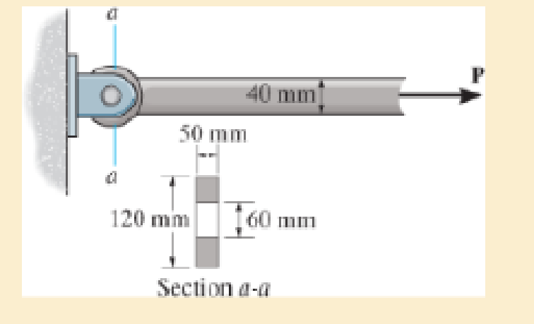
Chapter 1.7, Problem 1.21FP
Determine the maximum force P that can be applied to the rod if it is made of material having a yield stress of σY = 250 MPa. Consider the possibility that failure occurs in the rod and at section a–a. Apply a factor of safety of F. S. = 2 against yielding.
Expert Solution & Answer
Want to see the full answer?
Check out a sample textbook solution
Students have asked these similar questions
The assembly is used to support a distributed loading of w = 6.6
kN/m. The solid steel rod BC has a diameter of 13 mm and the steel
pins at A, B and C have a diameter of 10 mm. The yield stress of the
steel in tension is 250 MPa and in shear is 125 MPa.
C
1.2 m
0.9 m
0.3 m
Determine the factor of safety for the pin at B with respect to
yielding? Input your answer to two decimal places.
The cotter is used to hold the two rods together. Determine the smallest thickness t of the cotter and the smallest diameter d of the rods. All parts are made of steel for which the failure of normal stress is sfail = 500 MPa and the failure shear stress is tfail = 375 MPa. Use a factor of safety of (F.S.)t = 2.50 in tension and (F.S.)s = 1.75 in shear.
The bell-crank mechanism is in equilibrium for an applied load of F1 = 19 kN applied at A. Assume a = 270mm, b = 140mm, c = 75mm, and θ = 40°. Pin B is in a double-shear connection and has a diameter of 33 mm. The bell crank has a thickness of 39 mm. Determine(a) the shear stress in pin B.(b) the bearing stress in the bell crank at B.
Chapter 1 Solutions
Mechanics of Materials (10th Edition)
Ch. 1.2 - In each case, explain how to find the resultant...Ch. 1.2 - Determine the resultant internal normal force,...Ch. 1.2 - Determine the resultant internal normal force,...Ch. 1.2 - Determine the resultant internal normal force,...Ch. 1.2 - Determine the resultant internal normal force,...Ch. 1.2 - Determine the resultant internal normal force,...Ch. 1.2 - Determine the resultant internal normal force,...Ch. 1.2 - The shaft is supported by a smooth thrust bearing...Ch. 1.2 - Determine the resultant internal normal and shear...Ch. 1.2 - Determine the resultant internal loadings acting...
Ch. 1.2 - The shaft is supported by a smooth thrust bearing...Ch. 1.2 - Determine the resultant internal loadings acting...Ch. 1.2 - Determine the resultant internal loadings on the...Ch. 1.2 - Determine the resultant internal loadings at cross...Ch. 1.2 - The beam supports the distributed load shown....Ch. 1.2 - The beam supports the distributed load shown....Ch. 1.2 - The boom DF of the jib crane and the column DE...Ch. 1.2 - Determine the resultant internal loadings acting...Ch. 1.2 - Determine the resultant internal loadings acting...Ch. 1.2 - The blade of the hacksaw is subjected to a...Ch. 1.2 - The blade of the hacksaw is subjected to a...Ch. 1.2 - The beam supports the triangular distributed load...Ch. 1.2 - The beam supports the distributed load shown....Ch. 1.2 - The shaft is supported at its ends by two bearings...Ch. 1.2 - The shaft is supported at its ends by two bearings...Ch. 1.2 - The hand crank that is used in a press has the...Ch. 1.2 - Determine the resultant internal loadings acting...Ch. 1.2 - Determine the resultant internal loadings acting...Ch. 1.2 - The metal stud punch is subjected to a force of...Ch. 1.2 - Determine the resultant internal loadings acting...Ch. 1.2 - Determine the resultant internal loadings acting...Ch. 1.2 - Determine the resultant internal loadings acting...Ch. 1.2 - Determine the resultant internal loadings acting...Ch. 1.2 - The pipe has a mass of 12 kg/m. If it is fixed to...Ch. 1.2 - If the drill bit jams when the brace is subjected...Ch. 1.2 - The curved rod AD of radius r has a weight per...Ch. 1.2 - A differential element taken from a curved bar is...Ch. 1.5 - In each case, determine the largest internal shear...Ch. 1.5 - Determine the largest internal normal force in the...Ch. 1.5 - Determine the internal normal force at section A...Ch. 1.5 - The lever is held to the fixed shaft using the pin...Ch. 1.5 - The single-V butt joint transmits the force of 5...Ch. 1.5 - The uniform beam is supported by two rods AB and...Ch. 1.5 - Determine the average normal stress on the cross...Ch. 1.5 - Determine the average normal stress on the cross...Ch. 1.5 - If the 600-kN force acts through the centroid of...Ch. 1.5 - Determine the average normal stress at points A,...Ch. 1.5 - Determine the average normal stress in rod AB if...Ch. 1.5 - The supporting wheel on a scaffold is held in...Ch. 1.5 - Determine the largest intensity w of the uniform...Ch. 1.5 - The bar has a cross-sectional area A and is...Ch. 1.5 - The small block has a thickness of 0.5 in. If the...Ch. 1.5 - If the material fails when the average normal...Ch. 1.5 - If the block is subjected to a centrally applied...Ch. 1.5 - The plate has a width of 0.5 m. If the stress...Ch. 1.5 - The board is subjected to a tensile force of 200...Ch. 1.5 - The boom has a uniform weight of 600 lb and is...Ch. 1.5 - Determine the average normal stress in each of the...Ch. 1.5 - If the average normal stress in each of the...Ch. 1.5 - Determine the maximum average shear stress in pin...Ch. 1.5 - If P=5 kN, determine the average shear stress in...Ch. 1.5 - Determine the maximum magnitude P of the loads the...Ch. 1.5 - The column is made of concrete having a density of...Ch. 1.5 - The beam is supported by two rods AB and CD that...Ch. 1.5 - The beam is supported by two rods AB and CD that...Ch. 1.5 - If P = 15 kN, determine the average shear stress...Ch. 1.5 - The railcar docklight is supported by the...Ch. 1.5 - The plastic block is subjected to an axial...Ch. 1.5 - The two steel members are joined together using a...Ch. 1.5 - The bar has a cross-sectional area of 400(106) m2....Ch. 1.5 - The bar has a cross-sectional area of 400(106) m2....Ch. 1.5 - The two members used in the construction of an...Ch. 1.5 - The 2-Mg concrete pipe has a center of mass at...Ch. 1.5 - The 2-Mg concrete pipe has a center of mass at...Ch. 1.5 - The pier is made of material having a specific...Ch. 1.5 - Rods AB and BC have diameters of 4 mm and 6 mm,...Ch. 1.5 - The uniform bar, having a cross-sectional area of...Ch. 1.5 - The bar has a cross-sectional area of 400(106) m2....Ch. 1.5 - The bar has a cross-sectional area of 400(106) m2....Ch. 1.5 - The prismatic bar has a cross-sectional area A. If...Ch. 1.5 - The prismatic bar has a cross-sectional area A. If...Ch. 1.5 - The bars of the truss each have a cross-sectional...Ch. 1.5 - The bars of the truss each have a cross-sectional...Ch. 1.5 - Determine the largest load P that can be applied...Ch. 1.5 - Determine the greatest constant angular velocity ...Ch. 1.5 - The radius of the pedestal is defined by r =...Ch. 1.7 - Rods AC and BC are used to suspend the 200-kg...Ch. 1.7 - If it is subjected to double shear, determine the...Ch. 1.7 - Determine the maximum average shear stress...Ch. 1.7 - If each of the three nails has a diameter of 4 mm...Ch. 1.7 - The strut is glued to the horizontal member at...Ch. 1.7 - Determine the maximum average shear stress...Ch. 1.7 - If the eyebolt is made of a material having a...Ch. 1.7 - If the bar assembly is made of a material having a...Ch. 1.7 - Determine the maximum force P that can be applied...Ch. 1.7 - The pin is made of a material having a failure...Ch. 1.7 - If the bolt head and the supporting bracket are...Ch. 1.7 - Six nails are used to hold the hanger at A against...Ch. 1.7 - If A and B are both made of wood and are 38 in....Ch. 1.7 - Prob. 1.70PCh. 1.7 - The connection is made using a bolt and nut and...Ch. 1.7 - The tension member is fastened together using two...Ch. 1.7 - The steel swivel bushing in the elevator control...Ch. 1.7 - The spring mechanism is used as a shock absorber...Ch. 1.7 - Determine the size of square bearing plates A and...Ch. 1.7 - Determine the maximum load P that can be applied...Ch. 1.7 - Determine the required diameter of the pins at A...Ch. 1.7 - If the allowable tensile stress for wires AB and...Ch. 1.7 - If the allowable tensile stress for wires AB and...Ch. 1.7 - The cotter is used to hold the two rods together....Ch. 1.7 - Determine the required diameter of the pins at A...Ch. 1.7 - The steel pipe is supported on the circular base...Ch. 1.7 - The boom is supported by the winch cable that has...Ch. 1.7 - The boom is supported by the winch cable that has...Ch. 1.7 - The assembly consists of three disks A, B, and C...Ch. 1.7 - The two aluminum rods support the vertical force...Ch. 1.7 - The two aluminum rods AB and AC have diameters of...Ch. 1.7 - Determine the required minimum thickness t of...Ch. 1.7 - Determine the maximum allowable load P that can be...Ch. 1.7 - The compound wooden beam is connected together by...Ch. 1.7 - The hanger is supported using the rectangular pin....Ch. 1.7 - The hanger is supported using the rectangular pin....Ch. 1.7 - The rods AB and CD are made of steel. Determine...Ch. 1.7 - The aluminum bracket A is used to support the...Ch. 1.7 - If the allowable tensile stress for the bar is...Ch. 1.7 - The bar is connected to the support using a pin...Ch. 1 - The beam AB is pin supported at A and supported by...Ch. 1 - The long bolt passes through the 30-mm-thick...Ch. 1 - Determine the required thickness of member BC to...Ch. 1 - The circular punch B exerts a force of 2 kN on the...Ch. 1 - Determine the average punching shear stress the...Ch. 1 - The 150 mm by 150 mm block of aluminum supports a...Ch. 1 - The yoke-and-rod connection is subjected to a...Ch. 1 - The cable has a specific weight (weight/volume)...
Knowledge Booster


Learn more about
Need a deep-dive on the concept behind this application? Look no further. Learn more about this topic, mechanical-engineering and related others by exploring similar questions and additional content below.Similar questions
- Answer the ff. The bell-crank mechanism is in equilibrium for an applied load of F1 = 19 kN applied at A. Assume a = 330mm, b = 160mm, c = 75mm, and θ = 35°. Pin B is in a double-shear connection and has a diameter of 24 mm. The bell crank has a thickness of 28 mm. Determine(a) the shear stress in pin B.(b) the bearing stress in the bell crank at B.arrow_forwardThe bell-crank mechanism is in equilibrium for an applied load of F₁ = 18 kN applied at A. Assume a = 290mm, b = 170mm, c = 70mm, and 0 = 35°. Pin B is in a double-shear connection and has a diameter of 23 mm. The bell crank has a thickness of 37 mm. Determine (a) the shear stress in pin B. (b) the bearing stress in the bell crank at B. Support bracket Answers: Tpin 8 = i Bell crank i a B MPa MPa F₂arrow_forwardThe bell-crank mechanism is in equilibrium for an applied load of F1 = 11 kN applied at A. Assume a = 250mm, b = 100mm, c = 90mm, and θ = 40°. Pin B is in a double-shear connection and has a diameter of 29 mm. The bell crank has a thickness of 31 mm. Determine the shear stress in pin B. and the the bearing stress in the bell crank at B.arrow_forward
- The bell-crank mechanism is in equilibrium for an applied load of F1 = 17 kN applied at A. Assume a = 290mm, b = 120mm, c = 80mm, and e = 35°. Pin B is in a double-shear connection and has a diameter of 33 mm. The bell crank has a thickness of 36 mm. Determine (a) the shear stress in pin B. (b) the bearing stress in the bell crank at B. Bell crank F2 Support bracket A a Answers: Tpin B = MPa Ob = i MPaarrow_forwardThe pin is made of a material having a failure shear stress of tfail = 100 MPa. Determine the minimum required diameter of the pin to the nearest mm. Apply a factor of safety of F.S. = 2.5 against shear failure.arrow_forwardThe bell-crank mechanism is in equilibrium for an applied load of F₁ = 18 kN applied at A. Assume a = 270mm, b = 150mm, c = 70mm, and 0= 50°. Pin B is in a double-shear connection and has a diameter of 33 mm. The bell crank has a thickness of 39 mm. Determine (a) the shear stress in pin B. (b) the bearing stress in the bell crank at B. Support bracket F₁ Answers: Ob Tpin B = Bell crank Bu CI B MPa MPa F₂arrow_forward
- The bell-crank mechanism is in equilibrium for an applied load of F₁ = 12 kN applied at A. Assume a = 250mm, b = 170mm, c = 80mm, and 0 = 50°. Pin B is in a double-shear connection and has a diameter of 20 mm. The bell crank has a thickness of 25 mm. Determine (a) the shear stress in pin B. (b) the bearing stress in the bell crank at B. Support bracket A Answers: Tpin B = i Ob= i Bell crank a B b MPa MPaarrow_forwardThe bell-crank mechanism is in equilibrium for an applied load of F₁ = 11 kN applied at A. Assume a = 320mm, b = 170mm, c = 85mm, and 0 = 40%. Pin B is in a double-shear connection and has a diameter of 29 mm. The bell crank has a thickness of 23 mm. Determine (a) the shear stress in pin B. (b) the bearing stress in the bell crank at B. Bell crank F₂ Support bracket b MPa Answers: Tpin B = i Ob= i a MPaarrow_forwardThe bell-crank mechanism is in equilibrium for an applied load of F₁ = 13 kN applied at A. Assume a = 320mm, b = 130mm, c = 80mm, and = 45°. Pin B is in a double-shear connection and has a diameter of 31 mm. The bell crank has a thickness of 25 mm. Determine (a) the shear stress in pin B. (b) the bearing stress in the bell crank at B. Bell crank Support bracket Answers: Tpin B = i Ob = a B b MPa MPaarrow_forward
- The bell-crank mechanism is in equilibrium for an applied load of F1 = 11 kN applied at A. Assume a = 250mm, b = 100mm, c = 90mm, and θ = 40°. Pin B is in a double-shear connection and has a diameter of 29 mm. The bell crank has a thickness of 31 mm. Determine the shear stress in pin B. Express your answer in MPa rounded to the nearest hundredths.arrow_forwardThe bell-crank mechanism is in equilibrium for an applied load of F1 = 10 kN applied at A. Assume a = 260mm, b = 170mm, c = 70mm, and 0 = 40°. Pin B is in a double-shear connection and has a diameter of 20 mm. The bell crank has a thickness of 28 mm. Determine (a) the shear stress in pin B. (b) the bearing stress in the bell crank at B. Bell crank F2 Support bracket B A a b Farrow_forwardThe pin is made of a material having a failure shear stress of τfail = 125 MPa. Determine the minimum required diameter of the pin. Apply a factor of safety of F.S. = 2.5 against shear failure.arrow_forward
arrow_back_ios
SEE MORE QUESTIONS
arrow_forward_ios
Recommended textbooks for you
 Elements Of ElectromagneticsMechanical EngineeringISBN:9780190698614Author:Sadiku, Matthew N. O.Publisher:Oxford University Press
 Mechanics of Materials (10th Edition)Mechanical EngineeringISBN:9780134319650Author:Russell C. HibbelerPublisher:PEARSON
 Thermodynamics: An Engineering ApproachMechanical EngineeringISBN:9781259822674Author:Yunus A. Cengel Dr., Michael A. BolesPublisher:McGraw-Hill Education
 Control Systems EngineeringMechanical EngineeringISBN:9781118170519Author:Norman S. NisePublisher:WILEY
 Mechanics of Materials (MindTap Course List)Mechanical EngineeringISBN:9781337093347Author:Barry J. Goodno, James M. GerePublisher:Cengage Learning
 Engineering Mechanics: StaticsMechanical EngineeringISBN:9781118807330Author:James L. Meriam, L. G. Kraige, J. N. BoltonPublisher:WILEY
Elements Of Electromagnetics
Mechanical Engineering
ISBN:9780190698614
Author:Sadiku, Matthew N. O.
Publisher:Oxford University Press
Mechanics of Materials (10th Edition)
Mechanical Engineering
ISBN:9780134319650
Author:Russell C. Hibbeler
Publisher:PEARSON
Thermodynamics: An Engineering Approach
Mechanical Engineering
ISBN:9781259822674
Author:Yunus A. Cengel Dr., Michael A. Boles
Publisher:McGraw-Hill Education
Control Systems Engineering
Mechanical Engineering
ISBN:9781118170519
Author:Norman S. Nise
Publisher:WILEY
Mechanics of Materials (MindTap Course List)
Mechanical Engineering
ISBN:9781337093347
Author:Barry J. Goodno, James M. Gere
Publisher:Cengage Learning
Engineering Mechanics: Statics
Mechanical Engineering
ISBN:9781118807330
Author:James L. Meriam, L. G. Kraige, J. N. Bolton
Publisher:WILEY
An Introduction to Stress and Strain; Author: The Efficient Engineer;https://www.youtube.com/watch?v=aQf6Q8t1FQE;License: Standard YouTube License, CC-BY