
Videos
(a)
The value of
(a)
Answer to Problem 17.5P
The value of the resistance is
Explanation of Solution
Calculation:
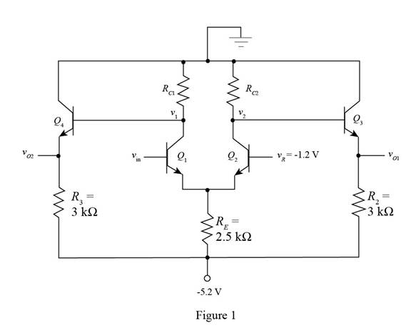
The given diagram is shown in Figure 1
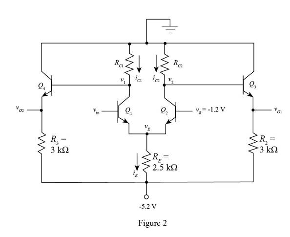
Mark the currents and redraw the circuit.
The required diagram is shown in Figure 2
The transistor number two is off and the value of the current
The expression for the value of the emitter voltage
Substitute
The expression for the value of the emitter current
Substitute
Substitute
The expression for the value of the capacitance of resistance
Substitute
Conclusion:
Therefore, the value of the resistance is
(b)
The value of the resistance
(b)
Answer to Problem 17.5P
The value of the resistance is
Explanation of Solution
Calculation:
The first transistor is on and the second is off.
The expression for the voltage
Substitute
The expression for the value of the emitter current
Substitute
The expression for the value of the current
Substitute
The expression for the value of the resistance
Substitute
Conclusion:
Therefore, the value of the resistance is
(c)
The value of the output voltage
(c)
Answer to Problem 17.5P
The case when the input voltage is
Explanation of Solution
Calculation:
Consider the case when the input voltage is
The expression to determine the value of the voltage
Substitute
The expression to determine the value of the voltage
Substitute
Consider the case when the input voltage is
The expression to determine the value of the voltage
Substitute
The expression to determine the value of the voltage
Substitute
Conclusion:
Therefore, the case when the input voltage is
(d)
The expression for the power dissipated in the circuit.
(d)
Answer to Problem 17.5P
The value of the power dissipated in the circuit for the input voltage
Explanation of Solution
Calculation:
Consider the case when the input voltage is
The expression for the value of the current through the resistance
Substitute
The expression for the value of the current through the resistance
Substitute
The expression for the value of the power dissipated in the circuit is given by,
Substitute
Consider the case when the input voltage is
The expression for the value of the current through the resistance
Substitute
The expression for the value of the current through the resistance
Substitute
The expression for the value of the power dissipated in the circuit is given by,
Substitute
Conclusion:
Therefore, the value of the power dissipated in the circuit for the input voltage
Want to see more full solutions like this?
Chapter 17 Solutions
MICROELECT. CIRCUIT ANALYSIS&DESIGN (LL)


- Evaluate and sketch the block diagram representation of the Direct Form I and IIfor the following IIR system function:arrow_forwardFor 4-bit R-2R Ladder Network DAC , if the Vref = 5V, and R = 20 Kohm, what is the output current for the following sequence: 1110 62.5 uA 15.625 uA 109.375 uA 218.75 uAarrow_forward4. Design DC voltage regulator for 6V output. Given data are: Vz= 6V at Iz = 20mA, Izk = 2mA, Pzmax = 500mW. The nominal input voltage is 15V±30% DC. Find the maximum current it can deliver to load.arrow_forward
- Which of the following annot be said of an L-Ccircuit? a.Exponentially decaying time response b.Tank circuit c.Sinusoidal response d.Oscillatorarrow_forwardTo demodulate the AM signal A,coswet + 4coswmtcoswet using envelope demodulation, the minimum value of Ac must be O a 1 O b. 3 Oc 2 O d. 4arrow_forwardAn. A/D converter uses 14-bit numbers linear sign magnitude PCM and has a voltage range of -6V to +6V. What is the resolution in μV of digitalization expressed as the smallest increment? (Use two decimal places for the final answer)arrow_forward
- 1கூ 1 Find the transfer function of these figure. 7 wi HT ை 2K2 1சீ PD%=}! @ 2•6} ©~•20secs). Vi (5) (3) 22, Vo (SI? P Vi (s)arrow_forward10. How to avoid DC signals to pass into output? O Using resistors on the output. O None of the mentioned. Using capacitors on the output. leaving the output port open O Using inductors on the output.arrow_forwardWhat are the small signal parameters of M1? a.)gm1 (in us) b.)ro1 (in MΩ)arrow_forward
- Q Given V s8086, v, assuming fvee space conditaus, find@ ED the Volume chargedensity atpso-5m tht charge lying closedsudace pso.6, o<21. Ans:-48-673U with in the ncarrow_forwardWhat type of A/D converter would work best for video signals with a frequency content up to 5 MHz? Why? (Our subject is Principles of Electronic Communications)arrow_forwardFor the system shown: a. Get the equations b. Simplify and determine C/R c. Draw the signal flow diagram for this system. H3 Z3 m1 R E E1 G1 G2 G3 G4 m n H2 Z1 22 H1arrow_forward
 Introductory Circuit Analysis (13th Edition)Electrical EngineeringISBN:9780133923605Author:Robert L. BoylestadPublisher:PEARSON
 Delmar's Standard Textbook Of ElectricityElectrical EngineeringISBN:9781337900348Author:Stephen L. HermanPublisher:Cengage Learning
 Programmable Logic ControllersElectrical EngineeringISBN:9780073373843Author:Frank D. PetruzellaPublisher:McGraw-Hill Education
 Fundamentals of Electric CircuitsElectrical EngineeringISBN:9780078028229Author:Charles K Alexander, Matthew SadikuPublisher:McGraw-Hill Education
 Electric Circuits. (11th Edition)Electrical EngineeringISBN:9780134746968Author:James W. Nilsson, Susan RiedelPublisher:PEARSON
 Engineering ElectromagneticsElectrical EngineeringISBN:9780078028151Author:Hayt, William H. (william Hart), Jr, BUCK, John A.Publisher:Mcgraw-hill Education,