
Electronics Fundamentals: Circuits, Devices & Applications
8th Edition
ISBN: 9780135072950
Author: Thomas L. Floyd, David Buchla
Publisher: Prentice Hall
expand_more
expand_more
format_list_bulleted
Videos
Textbook Question
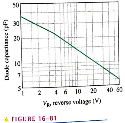
Chapter 16, Problem 35P
Figure 16-81 is a curve of reverse voltage versus capacitance for a certain varactor. Determine the change in capacitance if
Expert Solution & Answer
Want to see the full answer?
Check out a sample textbook solution
Students have asked these similar questions
Problem:
25 mH
m
Find Leq In below figure.
10 mH
m
60 mH
m
20 mH
m
30 mH
m
-o b
L
0000
the shunt capacitance is a capacitor
O a. Between a phase and the ground
O b. between phases and a phase to ground
c. none of the answers
O d. Between phases
Refer to Figure
If 50V is applied across the capacitors,
determine Q.
Write the answer in mC
30 μF 60 µF 20 µF
▬HE HE
C₁
C2
C 3
-
Chapter 16 Solutions
Electronics Fundamentals: Circuits, Devices & Applications
Ch. 16 - Silicon can be doped with a trivalent material...Ch. 16 - The minority carriers in an n-type material are...Ch. 16 - Before a diode fully conducts, the bias must...Ch. 16 - When forward bias is applied to a diode, the...Ch. 16 - The output frequency from a full-wave rectifier is...Ch. 16 - The peak output voltage of a full-wave bridge...Ch. 16 - If one diode is open in a bridge rectifier, the...Ch. 16 - Line regulation specifies how much change occurs...Ch. 16 - Normally, zener diodes, varactor diodes, and...Ch. 16 - Prob. 10TFQ
Ch. 16 - Â Atoms within a semiconductor crystal arc held...Ch. 16 - Free electrons exist in the valence band...Ch. 16 - Prob. 3STCh. 16 - The process of adding impurity atoms to a pure...Ch. 16 - Prob. 5STCh. 16 - The majority carriers in an n-type semiconductor...Ch. 16 - The pn junction is found in diodes silicon all...Ch. 16 - Prob. 8STCh. 16 - A fixed dc voltage that sets the operating...Ch. 16 - Prob. 10STCh. 16 - When a diode is forward-biased, it is blocking...Ch. 16 - Prob. 12STCh. 16 - The process of converting ac to pulsating dc is...Ch. 16 - Prob. 14STCh. 16 - The number of diodes used in a half-wave rectifier...Ch. 16 - If a 75 V peak sine wave is applied to a half-wave...Ch. 16 - The output frequency of a full-wave rectifier with...Ch. 16 - Two types of full-wave rectifier are single diode...Ch. 16 - When a diode in a center-tapped rectifier opens,...Ch. 16 - During the positive half-cycle of the input...Ch. 16 - The process of changing a half-wave or a full-wave...Ch. 16 - Prob. 22STCh. 16 - The zener diode is designed to operate in zener...Ch. 16 - Zener diodes are sometimes used as current...Ch. 16 - Varactor diodes are used as variable resistors...Ch. 16 - Prob. 26STCh. 16 - In a photodiode, light produces reverse current...Ch. 16 - List two semiconductive materials.Ch. 16 - How many valence electrons do semiconductors have?Ch. 16 - In a silicon crystal, how many covalent bonds does...Ch. 16 - What happens when heat is added to silicon?Ch. 16 - Name the two energy levels at which current is...Ch. 16 - Describe the process of doping and explain how it...Ch. 16 - What type of impurity is antimony? What type of...Ch. 16 - Explain what a hole is.Ch. 16 - What is recombination?Ch. 16 - How is the electric field across the pn junction...Ch. 16 - Because of its barrier potential, can a diode be...Ch. 16 - To forward-bias a diode, to which region must the...Ch. 16 - Prob. 13PCh. 16 - Explain how to generate the forward-bias portion...Ch. 16 - What would cause the barrier potential to decrease...Ch. 16 - Determine whether each diode in Figure 16-74 is...Ch. 16 - Determine the voltage across each diode in Figure...Ch. 16 - Examine the meter indications in each circuit of...Ch. 16 - Determine the voltage with respect to ground at...Ch. 16 - Calculate the average value of a half-wave...Ch. 16 - Prob. 21PCh. 16 - Can a diode with a PIV rating of 50 V be used in...Ch. 16 - Prob. 23PCh. 16 - Calculate the average value of a full-wave...Ch. 16 - Consider the circuit in Figure 16-79. What type of...Ch. 16 - Calculate the peak voltage rating of each half of...Ch. 16 - Prob. 27PCh. 16 - Prob. 28PCh. 16 - The ideal dc output voltage of a capacitor-input...Ch. 16 - Refer to Figure 16-80 and draw the waveforms VA...Ch. 16 - A certain voltage regulator has a no-load output...Ch. 16 - Prob. 32PCh. 16 - Prob. 33PCh. 16 - The VZ of a given zener diode changes 38 mV for a...Ch. 16 - Figure 16-81 is a curve of reverse voltage versus...Ch. 16 - Refer to Figure 16-81 and determine the value of...Ch. 16 - When the switch in Figure 16-82 is closed, will...Ch. 16 - Prob. 38PCh. 16 - From the meter readings in Figure 16-83, determine...Ch. 16 - Each part of Figure 16-84 shows oscilloscope...Ch. 16 - For each set of measured voltages at nodes 1 and 2...Ch. 16 - Determine the most likely failure in the circuit...Ch. 16 - Prob. 43PCh. 16 - Prob. 44PCh. 16 - Prob. 45PCh. 16 - Prob. 46PCh. 16 - Open file P16-47 and determine if there is a...Ch. 16 - Open file P16-48 and determine if there is a...Ch. 16 - Open file P16-49 and determine if there is a...Ch. 16 - Open file P16-50 and determine if there is a...Ch. 16 - Prob. 51PCh. 16 - Open file P16-52 and determine if there is a...
Knowledge Booster


Learn more about
Need a deep-dive on the concept behind this application? Look no further. Learn more about this topic, electrical-engineering and related others by exploring similar questions and additional content below.Similar questions
- An RC series circuit is connected to a 120-V, 60-Hz power source. The resistor is 25 and has a voltage drop of 65 volts. What is the capacitance of the capacitor?arrow_forwardBy convention, the sign of reactive power to an inductance is and the sign of reactive power to a capacitance isarrow_forwardfind total capacitance and total charge. C1 = 20pF C2 = 30pF 5V C3 = 30pF C5 10pF C4 30pFarrow_forward
- r cut 1oum 20gm 1ocm 个 //// wax poper/ A capacitur is mad by sandwiching a sheet of wax psper between two sheebs of aluminum fail, as shoumm What is the figue. capacitance! I the capacitoris aut into twopieces, alme the hme, what oil be the expacitenel of each Diece ? wiggly What lo be the capactncearrow_forwardM EXPERIMENT 01 V(n002) V(n001) 10V- 8V- 6V- 4V- 2V- OV- -2V- 4V- -6V- -8V- -10V- 0.00ms 30.00ms 60.00ms 90.00ms 120.00ms 150.00ms 180.00ms K EXPERIMENT 01 X Diode 1N914 V Resistor SINE(0 10 60000 100) 10K .tran 2arrow_forwardDetermine the equivalent inductance and equivalent current of the inductive circuit in Figure Q4. If L5 is replaced with a capacitor of 0.5 mF, how would it affect the branch current? The alternating Voltage source has an amplitude of 20 Vm. Vm Sine 50 Hz L1 5 mH L2 3 mH cele rele Figure Q4 rele celer L3 6.6 mH L4 2.8 mH reler L5 7 mHarrow_forward
- In a series LR circuit, the reactance of the inductance is 520 ohm. What will be the value of the inductor if the frequency of the AC is 60 HZ?arrow_forwardGiven the following Resistances and Capacitors in Series and Voltage Source: R1 = 6.946 ohms R2 = 9 485 ohms C1 - 0.731 Farad C2 - 0.925 Farad Vs - 15 Volts Frequency = 168 Hz What is the Capacitive Reactance of C1?arrow_forwardThe attached image shows a circuit with an AC voltage source, a resistor, inductor, and capacitor connected in series. The circuit has the following characteristics: Resistor resistance: 10 ohm Capacitor capacitance: 0.05 F Inductor inductance: 13 H Current Amplitude: 4 A Voltage amplitude across the source: 60 V Frequency at the source: 0.3 Hz Voltage amplitude across the resistor: 35 V Voltage amplitude across the capacitor: 37 V Voltage amplitude across the inductor: 80 V (a) Calculate the RMS voltages from the amplitudes above. From the RMS voltages across the capacitor, inductor and resistor, calculate the RMS voltage of the AC source. Hint: Vrms = V0/sqrt(2) Vrms = sqrt( (Vrms,R)2 + (Vrms, L - Vrms, C)2 ) (b) Calculate the RMS value of the current (c) Using the resistance, capacitance, inductance, and the frequency of the AC voltage, calculate the impedance Z. From this, and the previously measured value of Vrms, find the RMS value of the current in the circuit.arrow_forward
- iv. Change in DC voltage if capacitor increased to 100 F Vum-220 v - 50 Hz Ns Np=15 R=10KNarrow_forwardQ4. Determine the equivalent inductance and equivalent current of the inductive circuit in Figure Q4. If L5 is replaced with a capacitor of 0.5 mF, how would it affect the branch current? The alternating Voltage source has an amplitude of 20 Vm. Vm Sine 50 Hz L1 5 mH L2 3 mH Figure Q4 reee L3 6.6 mH L4 2.8 mH rele L5 7 mHarrow_forwardTwo series capacitors C1 and C2 are connected in series to a 24V battery. The dielectric for between the plates are K1=3.0 and K2= 4.0. Without any dielectric, capacitors C1 and C2 had equal capacitance of 5uF. What is the voltage across C2?arrow_forward
arrow_back_ios
SEE MORE QUESTIONS
arrow_forward_ios
Recommended textbooks for you
 Delmar's Standard Textbook Of ElectricityElectrical EngineeringISBN:9781337900348Author:Stephen L. HermanPublisher:Cengage Learning
Delmar's Standard Textbook Of Electricity
Electrical Engineering
ISBN:9781337900348
Author:Stephen L. Herman
Publisher:Cengage Learning
Inductors Explained - The basics how inductors work working principle; Author: The Engineering Mindset;https://www.youtube.com/watch?v=KSylo01n5FY;License: Standard Youtube License