
Electronics Fundamentals: Circuits, Devices & Applications
8th Edition
ISBN: 9780135072950
Author: Thomas L. Floyd, David Buchla
Publisher: Prentice Hall
expand_more
expand_more
format_list_bulleted
Concept explainers
Videos
Textbook Question
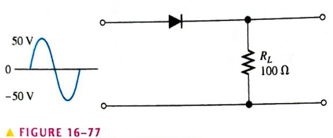
Chapter 16, Problem 22P
Can a diode with a PIV rating of 50 V be used in the circuit of Figure 16-77?
Expert Solution & Answer
Want to see the full answer?
Check out a sample textbook solution
Students have asked these similar questions
Figure shows the simple schematic of the diode circuit and the negative square wave input. What will be the output voltage value after the tenth revolution?Vi = 18V c1= 1 microF C2=47 microF (you can approximate by accepting C2 big c1
The answer is one of 3.83V, 3.33V, 3.56V, 2.76V and 1.78V.
4.
(d) the eedba
Calculate the oscillator frequency.
Determine the necessary value of R₂ in Figure 16-57 so that the circuit will oscillate. Neglect
the forward resistance of the zener diodes. (Hint: The total gain of the circuit must be 3 when
the zener diodes are conducting.)
Explain the purpose of R3 in Figure 16-57.
R₁
100 kQ
R2
www
ww-l
R$
1.0 ΚΩ
D₁
t
6.8 V 6.8 V
R3
www
47 kQ
enfren
D₂
www
‡
www.
C₁
0.015 F
R$
WWW
1.0 kn
C₂
0.015 F
V₁
During the positive input cycle shown, the conduction path is through diodes
a. Di and D2
b. Dz and D4
D1
D3
c. D1 and D4
Vin
d. D2 and D3
D2
D4
Chapter 16 Solutions
Electronics Fundamentals: Circuits, Devices & Applications
Ch. 16 - Silicon can be doped with a trivalent material...Ch. 16 - The minority carriers in an n-type material are...Ch. 16 - Before a diode fully conducts, the bias must...Ch. 16 - When forward bias is applied to a diode, the...Ch. 16 - The output frequency from a full-wave rectifier is...Ch. 16 - The peak output voltage of a full-wave bridge...Ch. 16 - If one diode is open in a bridge rectifier, the...Ch. 16 - Line regulation specifies how much change occurs...Ch. 16 - Normally, zener diodes, varactor diodes, and...Ch. 16 - Prob. 10TFQ
Ch. 16 - Â Atoms within a semiconductor crystal arc held...Ch. 16 - Free electrons exist in the valence band...Ch. 16 - Prob. 3STCh. 16 - The process of adding impurity atoms to a pure...Ch. 16 - Prob. 5STCh. 16 - The majority carriers in an n-type semiconductor...Ch. 16 - The pn junction is found in diodes silicon all...Ch. 16 - Prob. 8STCh. 16 - A fixed dc voltage that sets the operating...Ch. 16 - Prob. 10STCh. 16 - When a diode is forward-biased, it is blocking...Ch. 16 - Prob. 12STCh. 16 - The process of converting ac to pulsating dc is...Ch. 16 - Prob. 14STCh. 16 - The number of diodes used in a half-wave rectifier...Ch. 16 - If a 75 V peak sine wave is applied to a half-wave...Ch. 16 - The output frequency of a full-wave rectifier with...Ch. 16 - Two types of full-wave rectifier are single diode...Ch. 16 - When a diode in a center-tapped rectifier opens,...Ch. 16 - During the positive half-cycle of the input...Ch. 16 - The process of changing a half-wave or a full-wave...Ch. 16 - Prob. 22STCh. 16 - The zener diode is designed to operate in zener...Ch. 16 - Zener diodes are sometimes used as current...Ch. 16 - Varactor diodes are used as variable resistors...Ch. 16 - Prob. 26STCh. 16 - In a photodiode, light produces reverse current...Ch. 16 - List two semiconductive materials.Ch. 16 - How many valence electrons do semiconductors have?Ch. 16 - In a silicon crystal, how many covalent bonds does...Ch. 16 - What happens when heat is added to silicon?Ch. 16 - Name the two energy levels at which current is...Ch. 16 - Describe the process of doping and explain how it...Ch. 16 - What type of impurity is antimony? What type of...Ch. 16 - Explain what a hole is.Ch. 16 - What is recombination?Ch. 16 - How is the electric field across the pn junction...Ch. 16 - Because of its barrier potential, can a diode be...Ch. 16 - To forward-bias a diode, to which region must the...Ch. 16 - Prob. 13PCh. 16 - Explain how to generate the forward-bias portion...Ch. 16 - What would cause the barrier potential to decrease...Ch. 16 - Determine whether each diode in Figure 16-74 is...Ch. 16 - Determine the voltage across each diode in Figure...Ch. 16 - Examine the meter indications in each circuit of...Ch. 16 - Determine the voltage with respect to ground at...Ch. 16 - Calculate the average value of a half-wave...Ch. 16 - Prob. 21PCh. 16 - Can a diode with a PIV rating of 50 V be used in...Ch. 16 - Prob. 23PCh. 16 - Calculate the average value of a full-wave...Ch. 16 - Consider the circuit in Figure 16-79. What type of...Ch. 16 - Calculate the peak voltage rating of each half of...Ch. 16 - Prob. 27PCh. 16 - Prob. 28PCh. 16 - The ideal dc output voltage of a capacitor-input...Ch. 16 - Refer to Figure 16-80 and draw the waveforms VA...Ch. 16 - A certain voltage regulator has a no-load output...Ch. 16 - Prob. 32PCh. 16 - Prob. 33PCh. 16 - The VZ of a given zener diode changes 38 mV for a...Ch. 16 - Figure 16-81 is a curve of reverse voltage versus...Ch. 16 - Refer to Figure 16-81 and determine the value of...Ch. 16 - When the switch in Figure 16-82 is closed, will...Ch. 16 - Prob. 38PCh. 16 - From the meter readings in Figure 16-83, determine...Ch. 16 - Each part of Figure 16-84 shows oscilloscope...Ch. 16 - For each set of measured voltages at nodes 1 and 2...Ch. 16 - Determine the most likely failure in the circuit...Ch. 16 - Prob. 43PCh. 16 - Prob. 44PCh. 16 - Prob. 45PCh. 16 - Prob. 46PCh. 16 - Open file P16-47 and determine if there is a...Ch. 16 - Open file P16-48 and determine if there is a...Ch. 16 - Open file P16-49 and determine if there is a...Ch. 16 - Open file P16-50 and determine if there is a...Ch. 16 - Prob. 51PCh. 16 - Open file P16-52 and determine if there is a...
Knowledge Booster


Learn more about
Need a deep-dive on the concept behind this application? Look no further. Learn more about this topic, electrical-engineering and related others by exploring similar questions and additional content below.Similar questions
- When anode is negative as compared to cathode, diode is biased.arrow_forwardThe diodes in the circuit in Figure Q7 have V = 0.7. Determine the output voltage Vo and the currents Ip1, ID2, D3, and I for the following input conditions: V₁ = 2V V₂ = 3V *** In which all the diodes are ON state Parameter Valuc 101 = 6.05 A D2 = 665 9.05 N 9.65A 03 Vo = 5.725 1 - 10 - 19.50 -0.7 - 5 = 0.45m²ß U. = 10 19. H - (.45mA x 9.5 KR) = 5.725 W : 5.75 -02:22 0.5. k IN S. 725-0-7-7 6.05 m/ 3 4.0% XIU A 27 2 3 Vo 05 kQ 0.5 k 120 www IDI 1pz D₁ D₂ Figure Q7 +10 V lost [ f +5 V 9.5 KQ D ovo 77°F Cleararrow_forwardThere is a small amount of current across the barrier of a reverse-biased diode. This current is calledarrow_forward
- Show the output voltage for the Vi input voltage in the figure by drawing it along a period (Note: the diode used is a silicon diode, and it won't be considered an ideal diode) Vi R 15V Vi Vo * 5V -15Varrow_forwardDesign a clamper circuit to perform the function indicated. Vin Vout 10 V 5.7 v Vin DESIGN Vout -10 V -14.3 V Si diodesarrow_forward+2V D3 - tov 8,24 R -5V Di 12KR lok h OV Di, Dz and D3 ideal diodes. ane which diodes are on loff?arrow_forward
- Write down the name of the circuit and draw both input and output voltage waveshapes for Vin=10V, and R1=1KHZ and both the diodes D1 and D2 are silicon diodes. R1 D2 VIN VOUT 4V E 6Varrow_forwardC + + Vi = 20 V Vo peak to peak 5V The diode is a non- ideal with Vy = 0.7V Solve and draw the output waveform for the given clamper circuitarrow_forward* For the following circuit choose the correct output if the diodes are ideal R1 +10V V. 0 5 V 5 V -10 V +8.95 V +5 V- 5 V -18 V Vout O output +5.7V-- V 0 -5.7 V- Outputarrow_forward
- Draw the output waveform vo when V=5V and diode is idealarrow_forwardZener Diodes: In the following diagram, Iz = 0.5 mA, Vz = 5, rz = 30 ohms. What is Vout? What is the current through D5? Current through D7?arrow_forwardFind the load voltage VaL if all Zener diodes are Si with Vz = 5 v. O zero O 5.7 V O 1.4 V O 6.39 V O 10 V R, = 10 ka R - 4.7 ko 20 Varrow_forward
arrow_back_ios
SEE MORE QUESTIONS
arrow_forward_ios
Recommended textbooks for you
 Introductory Circuit Analysis (13th Edition)Electrical EngineeringISBN:9780133923605Author:Robert L. BoylestadPublisher:PEARSON
 Delmar's Standard Textbook Of ElectricityElectrical EngineeringISBN:9781337900348Author:Stephen L. HermanPublisher:Cengage Learning
 Programmable Logic ControllersElectrical EngineeringISBN:9780073373843Author:Frank D. PetruzellaPublisher:McGraw-Hill Education
 Fundamentals of Electric CircuitsElectrical EngineeringISBN:9780078028229Author:Charles K Alexander, Matthew SadikuPublisher:McGraw-Hill Education
 Electric Circuits. (11th Edition)Electrical EngineeringISBN:9780134746968Author:James W. Nilsson, Susan RiedelPublisher:PEARSON
 Engineering ElectromagneticsElectrical EngineeringISBN:9780078028151Author:Hayt, William H. (william Hart), Jr, BUCK, John A.Publisher:Mcgraw-hill Education,
Introductory Circuit Analysis (13th Edition)
Electrical Engineering
ISBN:9780133923605
Author:Robert L. Boylestad
Publisher:PEARSON
Delmar's Standard Textbook Of Electricity
Electrical Engineering
ISBN:9781337900348
Author:Stephen L. Herman
Publisher:Cengage Learning
Programmable Logic Controllers
Electrical Engineering
ISBN:9780073373843
Author:Frank D. Petruzella
Publisher:McGraw-Hill Education
Fundamentals of Electric Circuits
Electrical Engineering
ISBN:9780078028229
Author:Charles K Alexander, Matthew Sadiku
Publisher:McGraw-Hill Education
Electric Circuits. (11th Edition)
Electrical Engineering
ISBN:9780134746968
Author:James W. Nilsson, Susan Riedel
Publisher:PEARSON
Engineering Electromagnetics
Electrical Engineering
ISBN:9780078028151
Author:Hayt, William H. (william Hart), Jr, BUCK, John A.
Publisher:Mcgraw-hill Education,
Diodes Explained - The basics how diodes work working principle pn junction; Author: The Engineering Mindset;https://www.youtube.com/watch?v=Fwj_d3uO5g8;License: Standard Youtube License