
Electronics Fundamentals: Circuits, Devices & Applications
8th Edition
ISBN: 9780135072950
Author: Thomas L. Floyd, David Buchla
Publisher: Prentice Hall
expand_more
expand_more
format_list_bulleted
Concept explainers
Videos
Textbook Question
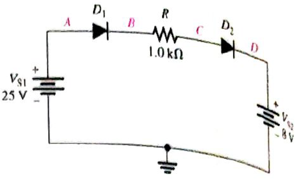
Chapter 16, Problem 19P
Determine the voltage with respect to ground at each point in Figure 16-76.
Expert Solution & Answer
Want to see the full answer?
Check out a sample textbook solution
Students have asked these similar questions
I need help with parts A - C please.
plz provide answer for ques6
part a and d
can you help with this plz thx
Chapter 16 Solutions
Electronics Fundamentals: Circuits, Devices & Applications
Ch. 16 - Silicon can be doped with a trivalent material...Ch. 16 - The minority carriers in an n-type material are...Ch. 16 - Before a diode fully conducts, the bias must...Ch. 16 - When forward bias is applied to a diode, the...Ch. 16 - The output frequency from a full-wave rectifier is...Ch. 16 - The peak output voltage of a full-wave bridge...Ch. 16 - If one diode is open in a bridge rectifier, the...Ch. 16 - Line regulation specifies how much change occurs...Ch. 16 - Normally, zener diodes, varactor diodes, and...Ch. 16 - Prob. 10TFQ
Ch. 16 - Â Atoms within a semiconductor crystal arc held...Ch. 16 - Free electrons exist in the valence band...Ch. 16 - Prob. 3STCh. 16 - The process of adding impurity atoms to a pure...Ch. 16 - Prob. 5STCh. 16 - The majority carriers in an n-type semiconductor...Ch. 16 - The pn junction is found in diodes silicon all...Ch. 16 - Prob. 8STCh. 16 - A fixed dc voltage that sets the operating...Ch. 16 - Prob. 10STCh. 16 - When a diode is forward-biased, it is blocking...Ch. 16 - Prob. 12STCh. 16 - The process of converting ac to pulsating dc is...Ch. 16 - Prob. 14STCh. 16 - The number of diodes used in a half-wave rectifier...Ch. 16 - If a 75 V peak sine wave is applied to a half-wave...Ch. 16 - The output frequency of a full-wave rectifier with...Ch. 16 - Two types of full-wave rectifier are single diode...Ch. 16 - When a diode in a center-tapped rectifier opens,...Ch. 16 - During the positive half-cycle of the input...Ch. 16 - The process of changing a half-wave or a full-wave...Ch. 16 - Prob. 22STCh. 16 - The zener diode is designed to operate in zener...Ch. 16 - Zener diodes are sometimes used as current...Ch. 16 - Varactor diodes are used as variable resistors...Ch. 16 - Prob. 26STCh. 16 - In a photodiode, light produces reverse current...Ch. 16 - List two semiconductive materials.Ch. 16 - How many valence electrons do semiconductors have?Ch. 16 - In a silicon crystal, how many covalent bonds does...Ch. 16 - What happens when heat is added to silicon?Ch. 16 - Name the two energy levels at which current is...Ch. 16 - Describe the process of doping and explain how it...Ch. 16 - What type of impurity is antimony? What type of...Ch. 16 - Explain what a hole is.Ch. 16 - What is recombination?Ch. 16 - How is the electric field across the pn junction...Ch. 16 - Because of its barrier potential, can a diode be...Ch. 16 - To forward-bias a diode, to which region must the...Ch. 16 - Prob. 13PCh. 16 - Explain how to generate the forward-bias portion...Ch. 16 - What would cause the barrier potential to decrease...Ch. 16 - Determine whether each diode in Figure 16-74 is...Ch. 16 - Determine the voltage across each diode in Figure...Ch. 16 - Examine the meter indications in each circuit of...Ch. 16 - Determine the voltage with respect to ground at...Ch. 16 - Calculate the average value of a half-wave...Ch. 16 - Prob. 21PCh. 16 - Can a diode with a PIV rating of 50 V be used in...Ch. 16 - Prob. 23PCh. 16 - Calculate the average value of a full-wave...Ch. 16 - Consider the circuit in Figure 16-79. What type of...Ch. 16 - Calculate the peak voltage rating of each half of...Ch. 16 - Prob. 27PCh. 16 - Prob. 28PCh. 16 - The ideal dc output voltage of a capacitor-input...Ch. 16 - Refer to Figure 16-80 and draw the waveforms VA...Ch. 16 - A certain voltage regulator has a no-load output...Ch. 16 - Prob. 32PCh. 16 - Prob. 33PCh. 16 - The VZ of a given zener diode changes 38 mV for a...Ch. 16 - Figure 16-81 is a curve of reverse voltage versus...Ch. 16 - Refer to Figure 16-81 and determine the value of...Ch. 16 - When the switch in Figure 16-82 is closed, will...Ch. 16 - Prob. 38PCh. 16 - From the meter readings in Figure 16-83, determine...Ch. 16 - Each part of Figure 16-84 shows oscilloscope...Ch. 16 - For each set of measured voltages at nodes 1 and 2...Ch. 16 - Determine the most likely failure in the circuit...Ch. 16 - Prob. 43PCh. 16 - Prob. 44PCh. 16 - Prob. 45PCh. 16 - Prob. 46PCh. 16 - Open file P16-47 and determine if there is a...Ch. 16 - Open file P16-48 and determine if there is a...Ch. 16 - Open file P16-49 and determine if there is a...Ch. 16 - Open file P16-50 and determine if there is a...Ch. 16 - Prob. 51PCh. 16 - Open file P16-52 and determine if there is a...
Knowledge Booster


Learn more about
Need a deep-dive on the concept behind this application? Look no further. Learn more about this topic, electrical-engineering and related others by exploring similar questions and additional content below.Similar questions
- Very urgent. Draw the waveforms of the voltage at the load (RL) end, the voltage at the R end, the voltage at the L end and the current 1 when the switch K is turned to position 2 after a long enough time.arrow_forwardpoint A and C onlyarrow_forwardA certain 2N5458 JFET has IDSS = 6.0 mA and VGS(off) = – 3.5 V.What is VGS at ID=3mA?arrow_forward
- The question is on the top left. Others are the details about it. Part A) CALCULATE RL PART B) CALCULATE RCarrow_forward17. Determine the voltage gain of the OTA in Figure 14–56. Assume K = 16 μS/μA for the graph in Figure 14-57.arrow_forwardQUESTION 3 A006 nF parallel plate capacitor with air between them has a separation between plates of 0.5 mm Determine t nel placer ino need to keyin unit of each plate in m²-885401ep fourarrow_forward
- What is the base voltage in figure 16 V 2.7 Ka 470 KQ B = 90 O 3.4 V O 1.5 V 0.7 V 4.3 Varrow_forward4. (d) the eedba Calculate the oscillator frequency. Determine the necessary value of R₂ in Figure 16-57 so that the circuit will oscillate. Neglect the forward resistance of the zener diodes. (Hint: The total gain of the circuit must be 3 when the zener diodes are conducting.) Explain the purpose of R3 in Figure 16-57. R₁ 100 kQ R2 www ww-l R$ 1.0 ΚΩ D₁ t 6.8 V 6.8 V R3 www 47 kQ enfren D₂ www ‡ www. C₁ 0.015 F R$ WWW 1.0 kn C₂ 0.015 F V₁arrow_forwardIn case of miss matched load O Reflection is unity O Reflection is partial only O Reflection is max Reflection is zeroarrow_forward
arrow_back_ios
SEE MORE QUESTIONS
arrow_forward_ios
Recommended textbooks for you
 Electricity for Refrigeration, Heating, and Air C...Mechanical EngineeringISBN:9781337399128Author:Russell E. SmithPublisher:Cengage Learning
 Delmar's Standard Textbook Of ElectricityElectrical EngineeringISBN:9781337900348Author:Stephen L. HermanPublisher:Cengage Learning
Electricity for Refrigeration, Heating, and Air C...
Mechanical Engineering
ISBN:9781337399128
Author:Russell E. Smith
Publisher:Cengage Learning
Delmar's Standard Textbook Of Electricity
Electrical Engineering
ISBN:9781337900348
Author:Stephen L. Herman
Publisher:Cengage Learning
Thevenin's Theorem; Author: Neso Academy;https://www.youtube.com/watch?v=veAFVTIpKyM;License: Standard YouTube License, CC-BY