
Videos
(a) Design the circuit shown in Figure P15.72 such that
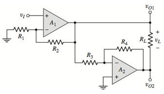
Figure P15.72
Want to see the full answer?
Check out a sample textbook solution
Chapter 15 Solutions
Microelectronics: Circuit Analysis and Design


- 45) We have buck converter, the maximum current of the inductor is Imax, the minimum inductor currentIs Imin. We now know the period of the switching signal is T=20 µs, the duty cycle D is 0.5, the load resistance R is 2 ohms, the input voltage is 30V, and the inductance L is 100 µH; What is Imax andIs Imin?arrow_forwardA boost regulator has L=0.15 mH and C=0.11 mF with a duty cycle of 0.66 at a switching frequency of 50 kHz. The average load current is la=0.5A. The maximum ripple output voltage is: Select one: a. None of these b. 1.6V C. 2.6V d. 0.6Varrow_forwardFor a Step-down chopper, design the circuit with 200ohm effective input resistance and 10ohm output resistance? Calculate the duty cycle and efficiency. Assume the input voltage accordingly.arrow_forward
- for the circuit if R = 5ohm, E = 20V and the cut-off (trigger) angle is 90 degrees; Draw the waveform of the source current Is, the output voltage VDC, and the output current Id Calculate the average value of output voltage VDC and output current Id.arrow_forwardA boost converter has an input voltage Vb-5V. The average load current is lo-0SA. The switching frequency is 25 kHz. Suppose that a regulator is added (L=0.15 mH and C-0.22 mF) and that the current is continuous. if the average output voltage is Vo =15V, then the ripple current of the inductor delta) is equal to: Select one: O a. None of these O b.0.89A O C. 1.41A O d. 0.56Aarrow_forward#has an input Q/The buck-boost regulator gu voltage of Vs = 12V. The duty cycle = 0.25 and the switching frequency is 25 KHZ. The inductance L = 150 μul and filter Capacitance C= 220 μf. The average load Current Ia = 1.25A. Determine (a) the average output voltage, Va (b) the peak-to-peak output voltage ripple, Avc (c) the peak-to-peak ripple current of inductor, AI (d) the peak Current of the transis () the critical values of L and C min. min.arrow_forward
- 6. Refer to the RC Phase-shift Oscillator below. A Vin R₁ + Rf 6.a. Derive the feedback factor formula for this circuit. 6.b. Draw the output waveform. C C mm C Vout wwwwwarrow_forwardAn RL load (R=0.2 Ohms, L=10 mH) is controlled by a converter. The supply voltage Vs is 600V and the chopper frequency is 200 Hz. The maximum peak to peak ripple current is equal to: Select one: a. 30A b. 55A c. 90A d. 75Aarrow_forwardQ2. For the circuit shown below, sketch i, & Vo 60 a. Find the conduction angle of the thyristor. b. Find the average output voltage V. R-6.50 f- Go Hz = 27AL = 120x17X10 = 6.4092 075 LO = RrjX= Vo L-17mH 6.5+j6.469=9.128 (44595 075 75V( Es 24 Vm A earrow_forward
- The condition for small signal analysis is VS must be less than 10mV vce vbe VCC O000arrow_forwardA boost converter is required to have an output voltage of 8 V and supply a load current of 1 A. The input voltage varies from 2.7 to 4.2 V. A control circuit adjusts the duty ratio to keep the output voltage constant. Select the switching frequency. Determine a value for the inductor such that the variation in inductor current is no more than 40 percent of the average inductor current for all operating conditions. Determine a value of an ideal capacitor such that the output voltage ripple is no more than 2 percent. Determine the maximum capacitor equivalent series resistance for a 2 percent ripple.arrow_forwardQ2. Find Q-point when VBB = 1V, 2 V and 3 V.. Assume VCE(sat) = 0 V. Re 1.0 KO Vcc RB www Bpc = 50 20 kN Draw the output waveform for the circuit shown belowarrow_forward
 Introductory Circuit Analysis (13th Edition)Electrical EngineeringISBN:9780133923605Author:Robert L. BoylestadPublisher:PEARSON
 Delmar's Standard Textbook Of ElectricityElectrical EngineeringISBN:9781337900348Author:Stephen L. HermanPublisher:Cengage Learning
 Programmable Logic ControllersElectrical EngineeringISBN:9780073373843Author:Frank D. PetruzellaPublisher:McGraw-Hill Education
 Fundamentals of Electric CircuitsElectrical EngineeringISBN:9780078028229Author:Charles K Alexander, Matthew SadikuPublisher:McGraw-Hill Education
 Electric Circuits. (11th Edition)Electrical EngineeringISBN:9780134746968Author:James W. Nilsson, Susan RiedelPublisher:PEARSON
 Engineering ElectromagneticsElectrical EngineeringISBN:9780078028151Author:Hayt, William H. (william Hart), Jr, BUCK, John A.Publisher:Mcgraw-hill Education,