
Concept explainers
Videos
a.
The expression for the switching point and the crossover voltages.
a.
Answer to Problem 15.50P
The switching voltage
The lower crossover voltage of Schmitt trigger is
The upper crossover voltage of Schmitt trigger is
Explanation of Solution
Given:
The circuit is given as:
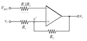
For the ideal operational amplifier, the currents in the inverting and the non-inverting terminal will be zero. By the virtual ground concept the inverting and the non-inverting node voltages will be equal.
Redrawing the circuit:
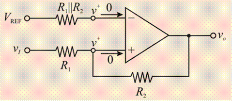
Applying nodal analysis at inverting node:
Applying nodal analysis at the non-inverting node:
Considering the
Hence, the switching voltage
Evaluating the upper crossover voltage of Schmitt trigger:
Hence, the upper crossover voltage of Schmitt trigger is
Evaluating the lower crossover voltage of Schmitt trigger:
Hence, the lower crossover voltage of Schmitt trigger is
b.
The R1 and VREF for the given condition.
b.
Answer to Problem 15.50P
The reference voltage is
Explanation of Solution
Given:
The circuit is given as:

The crossover voltages are
Substituting the
Hence,
Substitute,
Substitute
Hence,
Substituting,
Therefore, the reference voltage is
Substituting,
Hence, the reference voltage is
Want to see more full solutions like this?
Chapter 15 Solutions
Microelectronics: Circuit Analysis and Design


- What are the maximum rate and bandwidth of BPSK modulation?arrow_forwardC ompare the amplitude modullation and frequency modulations. What arethe advantages and disadvantages of both systems? (Please original answer not copy from internet)arrow_forwardDefine the following terms for FSK modulation: frequency deviation, modulation index, and deviation ratio.arrow_forward
- For an FM modulator with unmodulated carrier amplitude of Vc = 20cos(2π600Mhz t) and modulating signal of Vm= 8cos(2π10KHz t) a frequency deviation of 15kHz, and a load resistance RL = 10ohms. Determine the total power of the side frequencies A. 14.808W B. 0.1851W C. 0.93W D. 7.404arrow_forwardan fm broadcast station operates with a peak to peak deviation of 130 khz. calculate the percentage modulation determine the peak frequency deviation and modulation index for a frequency modulator with a deviation sensitivity of 10 khz/v and modulating signal of 5cos[2pi(2500)t] when the modulating frequency in an fm system is 500 hz and the modulating voltage is 2.6 v, the modulation index is 40. find the maximum deviation.what is the modulation index when the modulating frequency is raised to 800 hz and the modulating voltage is simultaneously reduced to 1.3 V what is the modulation index of an FM transmitter whose frequency deviation is 50 kHz whiter irs audio frequency is 10 kHz what is the deviation ratio of an FM signal if the maximum allowable deviation is 12 kHz and the maximum intelligence frequency of 4 kHzarrow_forwardHow might one determine general-direction MTF (modulation transfer function) to determine if there are any angular sensitivities to a camera system?arrow_forward
- Define modulation index. Why is it kept low? What is the role of a bandpass filter?arrow_forwardDiscuss the concept of multiplexing and its importance in optimizing bandwidth utilization.arrow_forwardGiven an FM modulator with a deviation sensitivity K1= 3.7 kHz/V and a modulating signal vm = 5.2 sin(2π1,906t), determine the carrier swing in kHz For an FM modulator with an unmodulated carrier amplitude Vc= 14 V, a modulation index m = 1, and a load resistance RL = 8 ohms, determine the power (in watts) in the modulated carrier The percent modulation of the sound portion of a TV signal is 85%. The maximum frequency deviation for the sound portion of the TV signal as specified by the FCC is 25 kHz. Determine the carrier swing (in kHz) of the signal. For an FM modulator with 40-kHz frequency deviation and a modulating-signal frequency fm= 13 kHz, determine the bandwidth (in kHz) using Carson's rule. Given an FM modulator with a deviation sensitivity K1= 1.4 kHz/V and a modulating signal vm = 3.9 sin(2π1,948t), determine the peak frequency deviation in kHz. The percent modulation of the sound portion of a TV signal is 73%. The maximum frequency deviation for the sound portion of the…arrow_forward
- Discuss the advantages and disadvantages of FSK modulation.arrow_forwardThe message signal m(t) into a FM modulator with the parameter kf=25 is shown in the following figure.a) Express the FM signal in time domain.b) Calculate and plot the frequency deviation in Hz.c) Calculate and plot the phase deviation in radians.arrow_forwardDraw block diagram /circuit diagram of the ff. FM circuits and discuss the operation. c. RATIO DETECTORarrow_forward
 Introductory Circuit Analysis (13th Edition)Electrical EngineeringISBN:9780133923605Author:Robert L. BoylestadPublisher:PEARSON
 Delmar's Standard Textbook Of ElectricityElectrical EngineeringISBN:9781337900348Author:Stephen L. HermanPublisher:Cengage Learning
 Programmable Logic ControllersElectrical EngineeringISBN:9780073373843Author:Frank D. PetruzellaPublisher:McGraw-Hill Education
 Fundamentals of Electric CircuitsElectrical EngineeringISBN:9780078028229Author:Charles K Alexander, Matthew SadikuPublisher:McGraw-Hill Education
 Electric Circuits. (11th Edition)Electrical EngineeringISBN:9780134746968Author:James W. Nilsson, Susan RiedelPublisher:PEARSON
 Engineering ElectromagneticsElectrical EngineeringISBN:9780078028151Author:Hayt, William H. (william Hart), Jr, BUCK, John A.Publisher:Mcgraw-hill Education,