Physics of Everyday Phenomena
9th Edition
ISBN: 9781259894008
Author: W. Thomas Griffith, Juliet Brosing Professor
Publisher: McGraw-Hill Education
expand_more
expand_more
format_list_bulleted
Concept explainers
Videos
Textbook Question
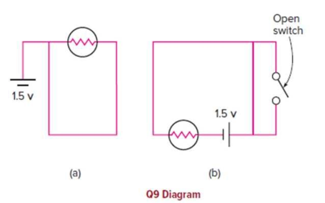
Chapter 13, Problem 9CQ
Two circuit diagrams are shown. Which one, if either, will cause the light bulb to light? Explain your analysis of each case.
Expert Solution & Answer
Want to see the full answer?
Check out a sample textbook solution
Students have asked these similar questions
You want to reduce your carbon footprint on the next Yuletide season, and so you plan to re-use the last year Christmas lights to your Christmas tree. You notice that one of the lightbulbs stops working. But you’re relieved to see the remainder of the lightbulbs are still in good condition. Which of the following is the correct hypothesis for the said situation?
Group of answer choices
The lights are connected in parallel circuit.
The lights are connected in a combination of series and parallel circuit.
The lights are connected in series circuit.
It would be impossible to determine the type of connection for the lights without dismantling the wiring.
The electric circuit shown at the right consists of a battery and three identical light bulbs. Which of the following statements are true concerning this circuit? List all that apply.
a. The current through point X will be greater than that through point Z.
b. The current through point Z will be greater than that through point Y.
c. The current will be the same through points X, Y and Z.
d. The current through point X will be greater than that through point Y.
e. The current through point Y will be greater than that through point X.
Question 1: Electric Circuits and Kirchhoff's Laws
In the circuit shown in the figure, ɛ1
R1 = 2kN, 1, = 2mA, and I, = 8mA.
10V, E2 = 8V,
%3D
a) Calculate R2.
b) Calculate R3.
c) Calculate the potential difference
between point a and point f
(AV = Vf – Va =?).
d) Draw a revised version of the
circuit that has an ammeter to measure the
e
current I, and a voltmeter to measure the
potential difference AV = V; – Va.
| +
Chapter 13 Solutions
Physics of Everyday Phenomena
Ch. 13 - Two arrangements of a battery, bulb, and wire are...Ch. 13 - Suppose you have two wires, a battery, and a bulb....Ch. 13 - In a simple battery-and-bulb circuit, is the...Ch. 13 - Are electric current and electric charge the same...Ch. 13 - When an axon is stimulated, a voltage spike or...Ch. 13 - Does the signal in an axon travel at the same...Ch. 13 - Consider the circuit shown, where the wires are...Ch. 13 - Consider the circuit shown. Could we increase the...Ch. 13 - Two circuit diagrams are shown. Which one, if...Ch. 13 - Suppose we use an uncoated metal clamp to hold the...
Ch. 13 - Consider the two signs shown, which are located in...Ch. 13 - If we decrease the potential difference across a...Ch. 13 - Prob. 13CQCh. 13 - When a battery is being used in a circuit, will...Ch. 13 - Two resistors are connected in series with a...Ch. 13 - In the circuit shown below. R1, R2,. and R3 are...Ch. 13 - In the circuit shown in question 16, which of the...Ch. 13 - If we disconnect R2, from the rest of the circuit...Ch. 13 - When current passes through a series combination...Ch. 13 - In the circuit shown, the circle with a V in it...Ch. 13 - In the circuit shown, the circle with an A in it...Ch. 13 - Which will normally have the larger resistance, a...Ch. 13 - Is electric energy the same as electric power?...Ch. 13 - If the current through a certain resistance is...Ch. 13 - Prob. 25CQCh. 13 - What energy source increases the potential energy...Ch. 13 - Prob. 27CQCh. 13 - Prob. 28CQCh. 13 - Prob. 29CQCh. 13 - Prob. 30CQCh. 13 - Prob. 31CQCh. 13 - Prob. 32CQCh. 13 - Why does a bimetallic strip bend when the...Ch. 13 - A charge of 28 C passes at a steady rate through a...Ch. 13 - A current of 4.5 A flows through a battery for 3...Ch. 13 - Prob. 3ECh. 13 - A current of 1.5 A is flowing through a resistance...Ch. 13 - A current of 0.522 A flows through a resistor with...Ch. 13 - Four 22 resistors are connected in series to an...Ch. 13 - A 47 resistor and a 28 resistor are connected in...Ch. 13 - In the circuit shown, the 1 resistance is the...Ch. 13 - Three resistors are connected to a 12-V battery as...Ch. 13 - Two resistors, each having a resistance of 40 ....Ch. 13 - Prob. 11ECh. 13 - Three identical resistances, each 30 , are...Ch. 13 - A 9-V battery in a simple circuit produces a...Ch. 13 - A 80 resistor has a voltage difference of 12 V...Ch. 13 - A 75-W light bulb operates on an effective ac...Ch. 13 - A toaster draws a current of 9.0 A when it is...Ch. 13 - A clothes dryer uses 6600 W of power when...Ch. 13 - In the circuit shown, the internal resistance of...Ch. 13 - Three 36 lightbulbs are connected in parallel to...Ch. 13 - In the circuit shown, the 8-V battery is opposing...Ch. 13 - In the combination of 12 resistors shown in the...Ch. 13 - A 850-W toaster, a 1200-W waffle iron, and a...
Knowledge Booster


Learn more about
Need a deep-dive on the concept behind this application? Look no further. Learn more about this topic, physics and related others by exploring similar questions and additional content below.Similar questions
- The circuit in Figure P27.34a consists of three resistors and one battery with no internal resistance. (a) Find the current in the 5.00- resistor. (b) Find the power delivered to the 5.00- resistor. (c) In each of the circuits in Figures P27.34b, P27.34c, and P27.34d, an additional 15.0-V battery has been inserted into the circuit. Which diagram or diagrams represent a circuit that requires the use of Kirchhoffs rules to find the currents? Explain why. (d) In which of these three new circuits is the smallest amount of power delivered to the 10.0- resistor? (You need not calculate the power in each circuit if you explain your answer.) Figure P27.34arrow_forwardA battery with an internal resistance of 10.0 produces an open circuit voltage of 12.0 V. A variable load resistance with a range from 0 to 30.0 is connected across the battery. (Note: A battery has a resistance that depends on the condition of its chemicals and that increases as the battery ages. This internal resistance can be represented in a simple circuit diagram as a resistor in series with the battery.) (a) Graph the power dissipated in the load resistor as a function of the load resistance. (b) With your graph, demonstrate the following important theorem: The power delivered to a load is a maximum if the load resistance equals the internal resistance of the source.arrow_forwardJumper cables are connected from a fresh battery in one car to charge a dead battery in another car. Figure P21.52 shows the circuit diagram for this situation. While the cables are connected, the ignition switch of the car with the dead battery is closed and the starter is activated to start the engine. Determine the current in (a) the starter and (b) the dead battery. (c) Is the dead battery being charged while the starter is operating? Figure P21.52 P21.52 Using Kirchhoffs rules and suppressing units, 12.0(0.01)I1(0.06)I3=0[1] 12.0+(1.00)I2(0.06)I3=0[2] andI1=I2+I3.[3] Substitute [3] into [1]: 12.0(0.01)(I2+I3)(0.06)I3=012.0(0.01)I2(0.07)I3=0[4] ANS. FIG. P21.52 Solving [4] and [2] simultaneously gives (a) I3 = 172 A = 172Adownward in the starter. (b) I2 = 1.70 A = 1.70Aupward in the dead battery. (c) No,thecurrentinthedeadbatteryisupwardinFigureP21.52,soitisnotbeingcharged.Thedeadbatteryisprovidingasmallamountofpowertooperatethestarter,soitisnotreallydead.arrow_forward
- Consider the circuit shown in Figure P28.21 on page 860. (a) Find the voltage across the 3.00-0 resistor, (b) Find the current in the 3.00-12 resistor.arrow_forwardA person with body resistance between his hands of 10.0k accidentally grasps the terminals of a20.0-kV power supply. (Do NOT do this!) (a) Draw a circuit diagram to represent the situation, (b) If the internal resistance of the power supply is 2000 , what is thecurrent through his body? (c) What is the power dissipated in his body? (d) If the power supply is to be made safe by increasing its internal resistance, what should the internal resistance be for the maximum current in this situation to be 1.00 mA or less? (e) Will this modification compromise the effectiveness of the power supply for driving low- resistance devices? Explain your reasoning.arrow_forwardThe rather simple circuit shown below is known as a voltage divider. The symbol consisting of three horizontal lines is represents “ground” and can be defined as the point where the potential is zero. The voltage divider is widely used in circuits and a single voltage source can be used to provide reduced voltage to a load resistor as shown in the second part of the figure, (a) What is the output voltage Vout of circuit (a) in terms of R1,R2,andVin (b) What is the output voltage Vout of circuit (b) in terms of R1,R2,RLandVinarrow_forward
- Is a circuit breaker wired (a) in series with the device it is protecting, (b) in parallel, or (c) neither in series or in parallel, or (d) is it impossible to tell?arrow_forwardWhen resistors with different resistances are connected in series, which of the following must be the same for each resistor? Choose all correct answers. (a) potential difference (b) current (c) power delivered (d) charge entering each resistor in a given time interval (e) none of those answersarrow_forwardYou have a faculty position at a community college and are m (caching a class in automotive technology. You are deep in a discussion of using jumper cables to start a car with a dead battery from a car with a fresh battery. You have drawn the circuit diagram in Figure P27.16 to explain the process. The battery on the left is the live batten- in the correctly functioning car, with emf and internal resistance RL where the L. subscript refers to live. Its terminals are connected directly across those of the dead battery, in the middle of the diagram, with emf and internal resistance RD where the D subscript refers to "dead Then, the starter in the car with the dead battery is activated by closing the ignition switch, allowing the car to start. The resistance of the starter is Rs. A student raises his hand and asks, So is the dead battery being charged while the starter is operating? How do you respond?arrow_forward
- Consider the circuits shown below, (a) What is the current through each resistor in part (a)? (b) What is the current through each resistor in part (b)? (c) What is the power dissipated or consumed by each circuit? (d) What is the power supplied to each circuit?arrow_forwardThe circuit shown in Figure P28.78 is set up in the laboratory to measure an unknown capacitance C in series with a resistance R = 10.0 M powered by a battery whose emf is 6.19 V. The data given in the table are the measured voltages across the capacitor as a function of lime, where t = 0 represents the instant at which the switch is thrown to position b. (a) Construct a graph of In (/v) versus I and perform a linear least-squares fit to the data, (b) From the slope of your graph, obtain a value for the time constant of the circuit and a value for the capacitance. v(V) t(s) In (/v) 6.19 0 5.56 4.87 4.93 11.1 4.34 19.4 3.72 30.8 3.09 46.6 2.47 67.3 1.83 102.2arrow_forwardThe terminals of a battery are connected across two resistors in series. The resistances of the resistors are not the same. Which of the following statements are correct? Choose all that are correct. (a) The resistor with the smaller resistance carries more current than the other resistor. (b) The resistor with the larger resistance carries less current than the other resistor. (c) The current in each resistor is the same. (d) The potential difference across each resistor is the same. (e) The potential difference is greatest across the resistor closest to the positive terminal.arrow_forward
arrow_back_ios
SEE MORE QUESTIONS
arrow_forward_ios
Recommended textbooks for you

 Principles of Physics: A Calculus-Based TextPhysicsISBN:9781133104261Author:Raymond A. Serway, John W. JewettPublisher:Cengage Learning
 Glencoe Physics: Principles and Problems, Student...PhysicsISBN:9780078807213Author:Paul W. ZitzewitzPublisher:Glencoe/McGraw-Hill
 Physics for Scientists and Engineers, Technology ...PhysicsISBN:9781305116399Author:Raymond A. Serway, John W. JewettPublisher:Cengage Learning
 Physics for Scientists and Engineers: Foundations...PhysicsISBN:9781133939146Author:Katz, Debora M.Publisher:Cengage Learning
 College PhysicsPhysicsISBN:9781938168000Author:Paul Peter Urone, Roger HinrichsPublisher:OpenStax College
Principles of Physics: A Calculus-Based Text
Physics
ISBN:9781133104261
Author:Raymond A. Serway, John W. Jewett
Publisher:Cengage Learning
Glencoe Physics: Principles and Problems, Student...
Physics
ISBN:9780078807213
Author:Paul W. Zitzewitz
Publisher:Glencoe/McGraw-Hill
Physics for Scientists and Engineers, Technology ...
Physics
ISBN:9781305116399
Author:Raymond A. Serway, John W. Jewett
Publisher:Cengage Learning
Physics for Scientists and Engineers: Foundations...
Physics
ISBN:9781133939146
Author:Katz, Debora M.
Publisher:Cengage Learning
College Physics
Physics
ISBN:9781938168000
Author:Paul Peter Urone, Roger Hinrichs
Publisher:OpenStax College
Ohm's law Explained; Author: ALL ABOUT ELECTRONICS;https://www.youtube.com/watch?v=PV8CMZZKrB4;License: Standard YouTube License, CC-BY