Videos
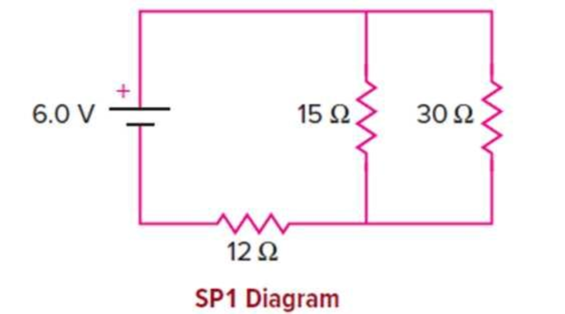
In the circuit shown, the internal resistance of the battery can be considered negligible.
a. What is the equivalent resistance of the two-resistor parallel combination?
b. What is the total current flowing through the battery?
c. What is the voltage drop across the 12-ohm resistor?
d. What is the voltage drop across the 15-ohm resistor?
e. What is the current flowing through the 15 Ω resistor?
f. What is the power dissipated in the 12 Ω resistor?
g. Is the current flowing through the 12 Ω resistor greater or less than that flowing through the 15 Ω resistor? Explain.
(a)
The equivalent resistance of the two parallel resistors.
Answer to Problem 1SP
The equivalent resistance of the two parallel resistors is
Explanation of Solution
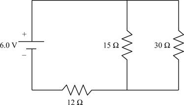
Given info: The given circuit is shown below.

In the given circuit the resistances
Write the formula for the equivalent resistance of two resistances connected in parallel.
Here,
Substitute
Conclusion:
The equivalent resistance of the two parallel resistors is
(b)
The total current flowing in the circuit.
Answer to Problem 1SP
The total current through the circuit is
Explanation of Solution
Given info: The given circuit is shown below.
In the given circuit the resistances
Write the formula for the total resistance of the circuit.
Here,
Write the formula for the total current in the circuit.
Here,
Substitute the expression of
From section (a) the equivalent resistance of the two parallel resistances is
Substitute
Conclusion:
The total current through the circuit is
(c)
The voltage drop across
Answer to Problem 1SP
The voltage drop across
Explanation of Solution
Given info: The given circuit is shown below.

In the given circuit the resistances
The voltage of the battery will get distributed among the
Write the formula for the voltage across the
Here,
From section (a) the equivalent resistance of the parallel connection is
Substitute
Conclusion:
The voltage drop across
(d)
The voltage drop across
Answer to Problem 1SP
The voltage drop across
Explanation of Solution
Given info: The given circuit is shown below.
In the given circuit the resistances
The voltage of the battery will get distributed among the
The voltage drop across
Write the formula for the voltage across the parallel connection of
Here,
From section (c) the voltage across the series resistor is
Substitute
Conclusion:
The voltage drop across
(e)
The current flowing through
Answer to Problem 1SP
The current flowing through
Explanation of Solution
Given info: The given circuit is shown below.

In the given circuit the resistances
Write the formula for current.
Here,
The voltage drop across
Substitute
Conclusion:
The current flowing through
(f)
The power dissipated in
Answer to Problem 1SP
The power dissipated in
Explanation of Solution
Given info: The given circuit is shown below.
In the given circuit the resistances
Write the formula for power.
Here,
From section (c) the voltage drop across
Substitute
Conclusion:
The power dissipated in
(g)
Whether the current through
Answer to Problem 1SP
The current through
Explanation of Solution
Given info: The given circuit is shown below.
In the given circuit the resistances
Since the current is a conserved quantity, in the given circuit, the current through
Conclusion:
The current through
Want to see more full solutions like this?
Chapter 13 Solutions
Physics of Everyday Phenomena


- Consider the circuits shown below, (a) What is the current through each resistor in part (a)? (b) What is the current through each resistor in part (b)? (c) What is the power dissipated or consumed by each circuit? (d) What is the power supplied to each circuit?arrow_forwardThe rather simple circuit shown below is known as a voltage divider. The symbol consisting of three horizontal lines is represents “ground” and can be defined as the point where the potential is zero. The voltage divider is widely used in circuits and a single voltage source can be used to provide reduced voltage to a load resistor as shown in the second part of the figure, (a) What is the output voltage Vout of circuit (a) in terms of R1,R2,andVin (b) What is the output voltage Vout of circuit (b) in terms of R1,R2,RLandVinarrow_forwardA person with body resistance between his hands of 10.0k accidentally grasps the terminals of a20.0-kV power supply. (Do NOT do this!) (a) Draw a circuit diagram to represent the situation, (b) If the internal resistance of the power supply is 2000 , what is thecurrent through his body? (c) What is the power dissipated in his body? (d) If the power supply is to be made safe by increasing its internal resistance, what should the internal resistance be for the maximum current in this situation to be 1.00 mA or less? (e) Will this modification compromise the effectiveness of the power supply for driving low- resistance devices? Explain your reasoning.arrow_forward
- Consider the circuit shown in Figure P28.9. Find (a) the current in the 20.0- resistor and (b) the potential difference between points a and b.arrow_forwardThree 100- resistors are connected as shown in Figure P28.5. The maximum power that can safely be delivered to any one resistor is 25.0 W. (a) What is the maximum potential difference that can be applied to the terminals a and b? (b) For the voltage determined in part (a), what is the power delivered to each resistor? (c) What is the total power delivered to the combination of resistors?arrow_forwardA 0.0200- ammeter is placed in series with a 10.00- resistor in a circuit, (a) Draw a circuit diagram of the connection, (b) Calculate the resistance of the combination, (c) If the voltage is kept the same across the combination as it was through the 10.00- resistor alone, what is the percent decrease in current? (d) If the current is kept the same through the combination as it was through the 10.00-resistor alone, what is the percent increase in voltage? (e) Are the changes found in parts (c) and (d) significant? Discuss.arrow_forward
- For the circuit shown in Figure P28.24, calculate (a) the current in the 2.00-11 resistor and (b) the potential difference between points a and b.arrow_forwardIn the circuit of Figure P28.30, determine (a) the current in each resistor and (b) the potential difference across the 200- resistor.arrow_forwardA 50resistor is connected across the emf v(t)=(160V)sin(120t) . Write an expression for the current throug1 the resistor.arrow_forward
- Consider the circuit shown in Figure P28.21 on page 860. (a) Find the voltage across the 3.00-0 resistor, (b) Find the current in the 3.00-12 resistor.arrow_forwardA car battery with a 12-V emf and an internal resistance of 0.050 is being charged with a current of 60 A. Note that in this process, the battery is being charged. (a)What is the potential difference across its terminals? (b)At what rate is thermal energy being dissipated in the battery? (c) At what rate is electric energy being converted into chemical energy?arrow_forwardA person with body resistance between his hands of 1.00 k accidentally grasps the terminals of a 20.0-kV power supply. (Do NOT do this!) (a) Draw a circuit diagram to represent the situation. (b) If the internal resistance of the power supply is 2000 , what is the current through his body? (c) What is the power dissipated in his body? (d) If the power supply is to be made safe by increasing its internal resistance, what should the internal resistance be for the maximum current in this situation to be 1.00 mA or less? (e) Will this modification compromise the effectiveness of the power supply for driving low-re si stance devices? Explain your reasoning,arrow_forward
 Physics for Scientists and Engineers: Foundations...PhysicsISBN:9781133939146Author:Katz, Debora M.Publisher:Cengage Learning
 Physics for Scientists and Engineers, Technology ...PhysicsISBN:9781305116399Author:Raymond A. Serway, John W. JewettPublisher:Cengage Learning
 College PhysicsPhysicsISBN:9781938168000Author:Paul Peter Urone, Roger HinrichsPublisher:OpenStax College
 Physics for Scientists and Engineers with Modern ...PhysicsISBN:9781337553292Author:Raymond A. Serway, John W. JewettPublisher:Cengage Learning
 Physics for Scientists and EngineersPhysicsISBN:9781337553278Author:Raymond A. Serway, John W. JewettPublisher:Cengage Learning