
Concept explainers
Videos
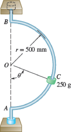
A small 250-g collar C can slide on a semicircular rod which is made to rotate about the vertical AB at a constant rate of 7.5 rad/s. Knowing that the coefficients of friction are μs = 0.25 and μk = 0.20, indicate whether the collar will slide on the rod if it is released in the position corresponding to (a) θ = 75°, (b) θ = 40°. Also, determine the magnitude and direction of the friction force exerted on the collar immediately after release.
Fig. P12.64 and P12.65
(a)
Indicate whether the collar will slide on the rod if it is released in the position corresponding to angle
Find the magnitude and direction of the friction force exerted on the collar immediately after release.
Answer to Problem 12.65P
The collar does not slide on the rod if it is released in the position corresponding to angle
The magnitude and direction of the friction force exerted on the collar immediately after release is 0.611 N.
Explanation of Solution
Given information:
The mass of collar (m) is 250 g.
The speed of rotation of semi-circular rod
The radius (r) of semicircular rod is 500 mm.
The coefficient of static friction
The coefficient of kinetic friction
Calculation:
The collar will not slide. Therefore the collar moves at constant speed.
Find the equation of radius of circle for constant rotation.
Find the equation of speed of semicircular rod for constant rotation:
Find the equation of normal acceleration
Substitute
Substitute
Sketch the free body diagram and kinetic diagram of the collar C as shown in Figure (1).
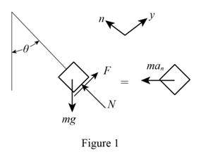
Refer Figure (1):
Find the normal force (N) on the collar.
Apply Newton’s law of equation along x-axis.
Substitute
Substitute 250 g for m,
Find the frictional force (F) using Newton’s law of equation:
Apply Newton’s law of equation along y-axis.
Substitute
Substitute 250 g for m,
Find the frictional force using general equation:
Substitute 0.25 for
The frictional force
Thus, the magnitude and direction of the friction force exerted on the collar immediately after release is 0.611 N.
(b)
Indicate whether the collar will slide on the rod if it is released in the position corresponding to angle
Find the magnitude and direction of the friction force exerted on the collar immediately after release.
Answer to Problem 12.65P
The collar does not slide on the rod if it is released in the position corresponding to angle
The magnitude and direction of the friction force exerted on the collar immediately after release is 0.957 N.
Explanation of Solution
Calculation:
Find the normal force (N) on the collar using Equation (1):
Substitute 250 g for m,
Find the frictional force (F) using Equation (2):
Substitute 250 g for m,
Find the frictional force using general equation:
Substitute 0.25 for
The frictional force
Sketch the free body diagram and kinetic diagram of the collar C which is sliding as shown in Figure (2).
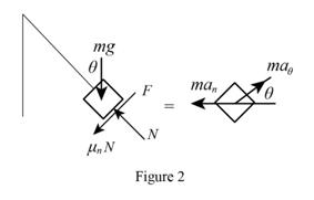
Refer Figure 2:
Find the normal force (N) on the collar.
Apply Newton’s law of equation along x-axis.
Substitute
Substitute 250 g for m,
Find the magnitude and direction of the friction force
Substitute 0.20 for
Thus, the magnitude and direction of the friction force exerted on the collar immediately after release is 0.957 N.
Want to see more full solutions like this?
Chapter 12 Solutions
VECTOR MECH...,STAT.+DYN.(LL)-W/ACCESS
Additional Engineering Textbook Solutions
Starting Out with C++ from Control Structures to Objects (9th Edition)
Problem Solving with C++ (10th Edition)
Mechanics of Materials (10th Edition)
Fluid Mechanics: Fundamentals and Applications
SURVEY OF OPERATING SYSTEMS
Database Concepts (8th Edition)


- Compute the mass fraction of eutectoid cementite in an iron-carbon alloy that contains 1.00 wt% C.arrow_forward! Required information Mechanical engineering, don't use chatgpt. Thanks A 60-kip-in. torque T is applied to each of the cylinders shown. NOTE: This is a multi-part question. Once an answer is submitted, you will be unable to return to this part. 3 in. 4 in. (a) (b) Determine the inner diameter of the 4-in. diameter hollow cylinder shown, for which the maximum stress is the same as in part a. The inner diameter is in.arrow_forwardMechanical engineering, Don't use chatgpt. Strict warning.arrow_forward
- 10:38 PM P 4136 54 A man Homework was due west for and 4km. He then changes directies walks on a bearing south-wes IS How far Point? of 1970 until he of his Starting Port Is he then from his stating What do you think about ... ||| Մ כarrow_forwardA simply supported T-shaped beam of 6m in length has to be designed to carry an inclined central point load W. Find the max- imum value of this load such that the maximum tensile and com- pression stresses on the beam do not exceed 30 and 60 respectively. N mm² N mm², 90 mm 80 mm Y W 60 mm 30° 10 mm 10 mm Xarrow_forwardProblem 9.5 9.5 A 1080-kg car is parked on a sloped street. The figure shows its wheels and the position of its center of mass. The street is icy, and as a result the coefficient of static friction between the car's tires and the street surface is μs = 0.2. Determine the steepest slope (in degrees relative to the horizontal) at which the car could remain in equilibrium if a. the brakes are applied to both its front and rear wheels; b. the brakes are applied to the front (lower) wheels only. Problem 9.5 1380 mm 532 mm 2370 mmarrow_forward
- Can someone explain please with conversionsarrow_forwardCorrect Answer is written below. Detailed and complete fbd only please. I will upvote, thank you. 1: The assembly shown is composed of a rigid plank ABC, supported by hinge at A, spring at B and cable at C.The cable is attached to a frictionless pulley at D and rigidly supported at E. The cable is made of steel with E = 200,000MPa and cross-sectional area of 500 mm2. The details of pulley at D is shown. The pulley is supported by a pin, passingthough the pulley and attached to both cheeks. Note that E is directly above B.Given: H = 3 m; L1 = 2 m; L2 = 4 m; w = 12 kN/m; x:y = 3:4Spring Parameters:Wire diameter = 30 mmMean Radius = 90 mmNumber of turns = 12Modulus of Rigidity = 80 GPaAllowable stresses:Allowable shear stress of Pin at D = 85 MPaAllowable normal stress of cheek at D = 90MPaAllowable bearing stress of cheek at D = 110MPa1. Calculate the reaction of spring Band tension in cable at C.2. Calculate the vertical displacementat C and the required diameter ofpin at D.3.…arrow_forwardCorrect answer and complete fbd only. I will upvote. The compound shaft, composed of steel,aluminum, and bronze segments, carries the two torquesshown in the figure. If TC = 250 lb-ft, determine the maximumshear stress developed in each material (in ksi). The moduliof rigidity for steel, aluminum, and bronze are 12 x 106 psi, 4x 10⁶ psi, and 6 x 10⁶ psi, respectivelyarrow_forward
- Can you explain the algebra steps that aren't shown but stated to be there, on how to get this equationarrow_forwardCorrect answer and complete fbd only. I will upvote. A flanged bolt coupling consists of two concentric rows of bolts. The inner row has 6 nos. of 16mm diameterbolts spaced evenly in a circle of 250mm in diameter. The outer row of has 10 nos. of 25 mm diameter bolts spaced evenly in a circle of 500mm in diameter. If the allowable shear stress on one bolt is 60 MPa, determine the torque capacity of the coupling. The Poisson’s ratio of the inner row of bolts is 0.2 while that of the outer row is 0.25 and the bolts are steel, E =200 GPa.arrow_forwardCorrect answer and complete fbd only. I will upvote. 10: The constant wall thickness of a steel tube with the cross sectionshown is 2 mm. If a 600-N-m torque is applied to the tube. Use G = 80 GPa forsteel.1. Find the shear stress (MPa) in the wall of the tube.2. Find the angle of twist, in degrees per meter of length.arrow_forward
 Elements Of ElectromagneticsMechanical EngineeringISBN:9780190698614Author:Sadiku, Matthew N. O.Publisher:Oxford University Press
 Mechanics of Materials (10th Edition)Mechanical EngineeringISBN:9780134319650Author:Russell C. HibbelerPublisher:PEARSON
 Thermodynamics: An Engineering ApproachMechanical EngineeringISBN:9781259822674Author:Yunus A. Cengel Dr., Michael A. BolesPublisher:McGraw-Hill Education
 Control Systems EngineeringMechanical EngineeringISBN:9781118170519Author:Norman S. NisePublisher:WILEY
 Mechanics of Materials (MindTap Course List)Mechanical EngineeringISBN:9781337093347Author:Barry J. Goodno, James M. GerePublisher:Cengage Learning
 Engineering Mechanics: StaticsMechanical EngineeringISBN:9781118807330Author:James L. Meriam, L. G. Kraige, J. N. BoltonPublisher:WILEY