
Engineering Circuit Analysis
9th Edition
ISBN: 9780073545516
Author: Hayt, William H. (william Hart), Jr, Kemmerly, Jack E. (jack Ellsworth), Durbin, Steven M.
Publisher: Mcgraw-hill Education,
expand_more
expand_more
format_list_bulleted
Concept explainers
Videos
Textbook Question
Chapter 12, Problem 13E
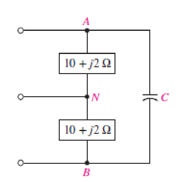
Referring to the balanced load represented in Fig. 12.33, if it is connected to a three-wire balanced source operating at 50 Hz such that VAN = 115 V, (a) determine the power factor of the load if the capacitor is omitted; (b) determine the value of capacitance C that will achieve a unity power factor for the total load.
Expert Solution & Answer
Want to see the full answer?
Check out a sample textbook solution
Students have asked these similar questions
Problem 2
For the system shown in Figure 12.5:
a) Find Is.
b) Find the average power delivered to each element.
c) Find the reactive power associated with each element.
d) Find PT, QT, and ST.
e) Find the power factor seen by the
source E.
R₁
ww
392
+
E = 50 V/60°
R3
ww
492
R₂
12 Ω Χ
16Ω
Xc
802
Figure 12.5
A parallel circuit of 25 – ohm resistor, 64 – mH inductor and 80 - μF capacitor connected across a 110 V, 50 Hz, single phase supply is shown in the figure below. Calculate: a.) the current in the individual element, b.) the total current drawn from the supply, c.) overall power factor of the circuit. Draw a neat phasor diagram showing IR, IL and IC.
A parallel circuit of 25 – ohm resistor, 64 – mH inductor and 80 - μF capacitor connected across a 110 V, 50 Hz, single phase supply is shown in the figure below. Calculate: a.) the current in the individual elementb.) the total current drawn from the supply c.) overall power factor of the circuit. Draw a neat phasor diagram showing IR, IL and IC.
Chapter 12 Solutions
Engineering Circuit Analysis
Ch. 12.1 - Let and . Find (a) Vad; (b) Vbc; (c) Vcd.Ch. 12.2 - Prob. 2PCh. 12.2 - Modify Fig. 12.9 by adding a 1.5 resistance to...Ch. 12.3 - A balanced three-phase three-wire system has a...Ch. 12.3 - A balanced three-phase three-wire system has a...Ch. 12.3 - Three balanced Y-connected loads are installed on...Ch. 12.4 - Each phase of a balanced three-phase -connected...Ch. 12.4 - Prob. 8PCh. 12.5 - Determine the wattmeter reading in Fig. 12.24,...Ch. 12.5 - Prob. 10P
Ch. 12 - Prob. 1ECh. 12 - Prob. 2ECh. 12 - Prob. 3ECh. 12 - Describe what is meant by a polyphase source,...Ch. 12 - Prob. 5ECh. 12 - Prob. 6ECh. 12 - Prob. 7ECh. 12 - Prob. 8ECh. 12 - Prob. 9ECh. 12 - Prob. 10ECh. 12 - The single-phase three-wire system of Fig. 12.31...Ch. 12 - Prob. 12ECh. 12 - Referring to the balanced load represented in Fig....Ch. 12 - Prob. 14ECh. 12 - Prob. 15ECh. 12 - Consider a simple positive phase sequence,...Ch. 12 - Assume the system shown in Fig. 12.34 is balanced,...Ch. 12 - Repeat Exercise 17 with Rw = 10 , and verify your...Ch. 12 - Prob. 19ECh. 12 - Prob. 20ECh. 12 - Prob. 21ECh. 12 - Prob. 22ECh. 12 - A three-phase system is constructed from a...Ch. 12 - Prob. 24ECh. 12 - Each load in the circuit of Fig. 12.34 is composed...Ch. 12 - Prob. 26ECh. 12 - Prob. 27ECh. 12 - A three-phase load is to be powered by a...Ch. 12 - For the two situations described in Exercise 28,...Ch. 12 - Prob. 30ECh. 12 - Prob. 31ECh. 12 - Prob. 32ECh. 12 - Repeat Exercise 32 if Rw = 1 . Verify your...Ch. 12 - Prob. 34ECh. 12 - Prob. 35ECh. 12 - Prob. 36ECh. 12 - A wattmeter is connected into the circuit of Fig....Ch. 12 - Find the reading of the wattmeter connected in the...Ch. 12 - (a) Find both wattmeter readings in Fig. 12.39 if...Ch. 12 - Circuit values for Fig. 12.40 are , , , , . Find...Ch. 12 - Prob. 41ECh. 12 - Prob. 42ECh. 12 - (a) Is the load represented in Fig. 12.41...Ch. 12 - Prob. 44E
Knowledge Booster


Learn more about
Need a deep-dive on the concept behind this application? Look no further. Learn more about this topic, electrical-engineering and related others by exploring similar questions and additional content below.Similar questions
- 1. A motor load consists of a resistance of 6 Ohms in series with an inductance of 12 mH. Assume 120Vac, 60 Hz supply. a. What is the complex impedance of the load? b. What is the ac current through this load? c. What is theta, the angle between voltage and current through this load? d. What is the power factor? e. What capacitance should be added in parallel with this load to correct the power factor to 1? f. What is the current from the supply when the power factor is corrected?arrow_forwardSHOW COMPLETE SOLUTION. A. Determine the resistance component of Load 2. Use ohm's law and two decimal places. B. A capacitor will be connected in parallel with the source and the loads. What must be the value of this capacitor in microfarads to increase the overall power factor seen by the source to unity or 1.0? Use two decimal places.arrow_forward(e) The load in milling factory is having active and reactive power of 100 kW and 59.33 kVAr, respectively at voltage supply of 415 V. A capacitor bank system (PFC) with voltage rating 515 V is to be installed with the target to increase the power factor to 95%. The PFC has the step arrangement of 1:1:2:2:3:3 with 5 kVAr for each capacitor unit. (i) Analyse the average power factor and the minimum effective reactive power, Os injected into supply system. (ii) Examine the effective reactive power, Qceff to be supplied by capacitor bank and the total unit steps of power factor corrector to be (iii) Estimate the actual average power factor for the system based on the unit step recommended in Q(e)(ii). (iv) Justify the implication of total unit steps of power factor corrector if 3.3kVAr per unit of capacitor is to be used in the factory.arrow_forward
- A 440Vrms, 60-Hz source supplies two loads connected in parallel : Load 1(L1): 12 kVA, 0.70 pf lagging Load2 (L2): 10 kVA, 0.80 pf lagging (a) Find the p.f. of the parallel combination. (b) Calculate the capacitance connected in parallel that will raise the power factor to unity.arrow_forwardThree Impedances each of (8 - j24)2 are connected in mesh across a three-phase 420V ac supply. Determine the phase current, line current, active power, reactive power drawn from supply. Also draw the Phasor diagram for the mesh connection and marks the Line current ,phase current line voltage and phase angle between phase current and pahse voltage. phase current (Ip) Line current real power reactive powerarrow_forwardTwo impedances consist of resistance of (15 ohms and series connectedinductance of 0.04 henry) and (resistance of 10 ohms, inductance of 0.1 henryand a capacitance of 100 microfarad, all in series) are connected in series andare connected to 230 volts, 50 – Hz AC source. Find: (a) current drawn, (b) voltageacross each impedance, (c) individual and total power factor. Draw the phasordiagram.arrow_forward
- By using the circuit given below; a) of the system. b) c) d) Find the total value of active power, reactive power, apparent power, and power factor Draw the power triangle. Find the current drawn from the source. Find the equivalent impedance that seen from the source side. 2000 VAR CosØ=0.6 (leading) 5 kVA 2204V 50 Hz CosØ=0.65 (lagging)arrow_forwardA 5-ohm resistor is connected in series with a 25 micro-farad capacitor. A source voltage of 158 volts, 50 Hz supplies the combination. Determine the following: a. Circulating current b. Voltage across the resistor c. Voltage across the capacitor d. Real power supplied by the source e. Reactive power supplied by the source f. Apparent power of the circuit g. Power factor of the entire circuitarrow_forwardA threephase, balanced load is star (wye) connected and consumes 180 kW from the grid (400Vrms@50Hz). A capacitor bank (also balanced) of 65 kVAr is connected in parallel. As a result the total power factor equals 0.90. a) Determine the power factor of the load (so without capacitor bank. b) The capacitor bank is delta connected. Determine the capacitance of the capacitors.arrow_forward
- low voltage systems In the reverse phase, a 1000 kw powerful load under 0.5 power factor is fed from a 5 kv source.A capacitor is connected in parallel with the load to increase the power factor to 0.8. a-) Find the required capacitor power. b-) Compare the apparent power before and after compensation.arrow_forwardProblem 4 Two loads are connected in parallel across a 1000-V rms, 60-Hz source. One load absorbs 450 kW at 0.6 power factor lagging, and the second load absorbs 500 kW and 400 KVAR. Determine the value of the capacitor that should be added in parallel with the two loads to improve the overall power factor to 0.9 lagging.arrow_forward8. A parallel circuit of 25 – ohm resistor, 64 – mH inductor and 80 - μF capacitor connected across a 110 V, 50 Hz, single phase supply is shown in the figure below. Calculate the current in the individual element, the total current drawn from the supply and overall power factor of the circuit. Draw a neat phasor diagram showing IR, IL and IC.arrow_forward
arrow_back_ios
SEE MORE QUESTIONS
arrow_forward_ios
Recommended textbooks for you
 Power System Analysis and Design (MindTap Course ...Electrical EngineeringISBN:9781305632134Author:J. Duncan Glover, Thomas Overbye, Mulukutla S. SarmaPublisher:Cengage Learning
Power System Analysis and Design (MindTap Course ...
Electrical Engineering
ISBN:9781305632134
Author:J. Duncan Glover, Thomas Overbye, Mulukutla S. Sarma
Publisher:Cengage Learning
Capacitors Explained - The basics how capacitors work working principle; Author: The Engineering Mindset;https://www.youtube.com/watch?v=X4EUwTwZ110;License: Standard YouTube License, CC-BY