
Videos
Chemical/Bio Engineering
Figure P12.12 depicts a chemical exchange process consisting of a series of reactors in which a gas fl owing from left to right is passed over a liquid fl owing from right to left. The transfer of a chemical from the gas into the liquid occurs at a rate that is proportional to the difference between the gas and liquid concentrations in each reactor. At steady state, a mass balance for the first reactor can be written for the gas as
and for the liquid as
Where
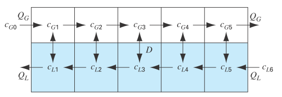
FIGURE P12.12
To calculate: The flow rate of the flow through every pipe if the flow equation through he reactors is provided by following system of equations:
For gas it is provided as:
And for liquid it is provided as:
Answer to Problem 12P
Solution: The concentration of liquid and gases in the reactor is:
Explanation of Solution
Given Information:
The system of reactors is provided as follows:
Flow rate and the concentration are provided as:
Formula used:
Write system of linear equations in matrix form.
And,
The term
Calculation:
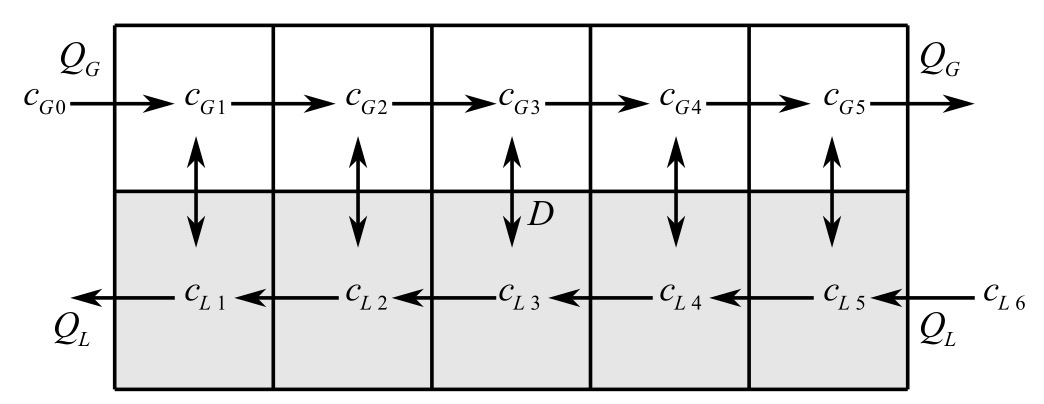
Consider the figure below,
Here,
For reactor 1, the system is in steady state. Therefore, themass balance equation for the gas reactor 1.
Substitute
For reactor 2, the system is in steady state. Therefore, the mass balance for the gas reactor 2 is,
Substitute
For reactor 3, the system is in steady state, therefore, the mass balance equation for the gas reactor 3 is,
Substitute
For reactor 4, the system is in steady state. Therefore, the mass balance for the gas reactor 4 is,
Substitute
For reactor 5, the system is in steady state. Therefore, the mass balance for the gas reactor 5 is,
Substitute
For reactor 1, the system is in steady state. Therefore, the mass balance for the liquid reactor 1 is,
Substitute
For reactor 2, the system is in steady state. Therefore, the mass balance for the liquid reactor 2 is,
Substitute
For reactor 3, the system is in steady state. Therefore, the mass balance for the liquid reactor 3 is,
Substitute
For reactor 4, the system is in steady state. Therefore, the mass balance for the liquid reactor 4 is,
Substitute
For reactor 5, the system is in steady state. Therefore, the mass balance for the liquid reactor 5 is,
Substitute
Now, recollect all the linear equations for mass balance equation of gases and liquids.
There are too many linear equations which is complex to solving manually. So, write the equation in the form ofmatrices that is augmented form as shown below:
With the help of the linear system of equations provided above, the coefficient matrix A is,
With the help of the linear system of equations provided above, the column matrix X is:
And With the help of the linear system of equations provided above, the column matrix D is,
Write the system of equation in the augmented form.,
Solve the matrix
MATLAB is used to perform the calculation, type the following code into MATLAB cmd.
Once you press eneter, the resut is obtained as follows:
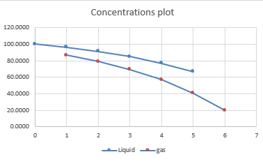
Hence, the values of concentrations passing through the reactors is shown in the below table:
The plot of concentration of liquid and gas is provided as:
Want to see more full solutions like this?
Chapter 12 Solutions
EBK NUMERICAL METHODS FOR ENGINEERS
Additional Engineering Textbook Solutions
Advanced Engineering Mathematics
Fundamentals of Differential Equations (9th Edition)
Basic Technical Mathematics
STATS:DATA+MODELS-W/DVD
Intermediate Algebra (8th Edition)


- 3 A farmer has a 10-heactare maize farm. The maize is under “Fall Army Worm” attack. The farmer has to urgently control the attack using a chemical called AGENOX 221. Motorized sprayers with tank capacities of 15 litres each are to be used. The recommended concentration of the chemical is 2 ml/L and each full tank will cover ½ hectare. A 50-man team is engaged to control the attack. Using the above information and the assumptions given below: i. What volume of the chemical is required to cover the entire field to control the “Fall Army Worm” attack? ii. If each man covers an area of 25 m2 from one end of the field to the other, how many trips will each of them make to cover the entire field? Assume ach man moves in a straight line. Assumptions: 1. The 10 ha farm is considered to be a perfect square. 2. There is a 2.5 % loss of chemical due to the transfer to the sprayer tank.arrow_forwardEquations of Polytropic Process Definition, diagrams, equations, & sample problems Test Your Skills 14.1 1. A substance undergoes a process such that pV13 = C. If during this process the volume increases by 25% and the initial temperature is 300 K, find the final temperature in K. Your answer Submit Previous activity Jumn to 合曲 60000arrow_forwardProblem 2. Fluid circulates steadily through four devices in a power plant as shown in the sketch. Mass flow rates and enthalpies per unit mass are tabulated for some of the states. Heat- and work-interaction råtes are tabulated for some of the devices. Complete the following tables: h State (kg/s) (J/kg) Device (W) (W) A D B 1 15 A. 150 2 13 30 3 25 C 3. 4. 5arrow_forward
- A cryogenic substance is found to have a specific heat capacity (at constant volume) c_v that varies with temperature according to c_v = AT^2, where A is an empirically derived constant with units J/(K^3 kg). If 220 J of energy must be transferred thermally (at constant volume) to an 8,750 mg sample of this substance to raise the temperature of the sample from 1.0 K to 6.6 K, what is the value of A? Your Answer: Answer unitsarrow_forwardThermochemistry Assignment 26.4: An ice cube with a mass of 103 grams and an initial temperature of 0°C is added in an adiabatic container with 2L of water initially at 25°C. Using the data given below, answer the ff. questions: Water as Liquid as Ice Density (g/mL) Cp (Joule/K-mole) AHusion (KJ/mole) AHvaportzation (KJ/mole) 1.000 0.997 75.35 37.71 6.01 40.57 1. What is the mass of ice that melt at the equilibrium state? 2. What is the mass of ice that will remain unmelted at the equilibrium state? 3. Calculate the absolute temp. at the equilibrium state.arrow_forwardThermal resistance for conduction across a slab is inversely proportional to the thickness of the slab. directly proportional to the cross-sectional area of the slab. inversely proportional to the cross-sectional area of the slab. directly proportional to the conductivity of the slab. Conduction through a one-dimensional slab without any heat generation at steady state. The temperature profile inside the slab is parabolic. linear. logarithmic. constantarrow_forward
- A closed thermodynamic system consists of a fixed amount of substance (i.e. mass) in which no substance can flow across the boundary, but energy can. For a closed themodynamic system we cannot add energy to the system, via substance (E ) (1.e. matter which contains energy is not allowed across the boundary) Across the Boundaries E° = No Q = = Yes W mass NO CLOSED = Yes SY STEM m = constant | energy YES Figure 1.1. If the substance inside the thermodynamic system shown in figure 1.1. (i.e. piston cylinder device) is air, is the system a Fixed closed system Moveable closed system A. В.arrow_forward3. Laws on Conservation. Using the energy model sketched below plus concepts of energy conservation, consider the impact of a dirty war on the global energy. To start, assume that the impact of this war has created an atmosphere that absorbs 75% of the incoming sunlight, while the albedo is reduced to nearly 20%. Let's assume that Earth's ability to reflect incoming solar radiation is negligible. The Earth's surface radiates 240 W/m2, all of which is absorbed by the atmosphere. Assuming that Earth can be modeled as a blackbody emitter and incoming/outgoing energy as shown in the schematic, find the following quantities: a) The "nuclear winter" temperature [°C] of the surface of the Earth b) X, the rate [W/m²] at which radiation is emitted from the atmosphere to space c) Y, the rate [W/m²] of absorption of short-wavelength solar radiation at the Earth's surface d) Z, the rate [W/m2] at which the atmosphere radiates energy to the Earth's surface Incoming 342 W/m² Reflected to space X…arrow_forward1. For your science fair project, you decided to design a model rocket ship. The fuel burns exerting a time-varying force on the small 2.00 kg rocket model during its vertical launch. This force obeys the equation F= A + Bt2. Measurements show that at t=0, the force is 25.0 N, and at the end of the first 2.00 s, it is 45.0 N. Assume that air resistance is negligible. a. What are the forces acting on the rocket? b. Draw its free-body diagram. c. Find the constants A and B, including their SI units using this equation F= A + Bt². d. Find the net force on this rocket and its acceleration the instant after the fuel ignites. e. Find the net force on this rocket and its acceleration 3.00 s after fuel ignition. f. Suppose you were using this rocket in outer space, far from all gravity. What would its acceleration be 3.00 s after fuel ignition? g. What is the rocket's mass in outer space? What is its weight?arrow_forward
- a) In periodic motion, it is often interesting to investigate the harmonic motion of an object. The decrease in amplitude caused by dissipative force is called damping, and the corresponding motion is called damped oscillation. Damped oscillation is governed by the following equation, where is the angular frequency of oscillation, A is the initial amplitude of the oscillation, m is the mass of an object, b is a constant that describes the strength of the damping force, t is time in seconds, h is the ratio between a force constant k and the mass m: where x(t) = Ae sin(at + p) If = 60°, A = 4, v = 2m @= h b² 4m² b = 0.25, create a plot x(t) for 0≤t≤ 15, with h = 4. Label all the axes, 2m include gridlines and provide a title in your plot.arrow_forwardFive moles of gas initially at a pressure of 2.00 atm and a volume of 0.300 L has internal energy equal to 91.0 J. In its final state, the gas is at a pressure of 1.50 atm and a volume of 0.800 L, and its internal energy equals 182 J. P (atm) 2.00 B 1.50 V (liters) 0.300 0.800 (a) For the paths IAF, IBF, and IF in the figure above, calculate the work done on the gas. WIAF= W IBF= WIF = (b) For the paths IAF, IBF, and IF in the figure above, calculate the net energy transferred to the gas by heat in the process. QIAF= QIBF=| Need Help? Read Itarrow_forward= 14 15 16 17 18 19 20 21 22 23 24 25 26 A gas storage cylinder in an ordinary chemical laboratory measures 3.9 cm wide and 16. cm high. This is the label on it. olo Contents: N, gas Pressure: 7.93 atm If the cylinder is opened and the gas allowed to escape into a large empty plastic bag, what will be the final volume of nitrogen gas, including what's collected in the plastic bag and what's left over in the cylinder? Write your answer in liters. Round your answer to 2 significant digits. ?arrow_forward
 Elements Of ElectromagneticsMechanical EngineeringISBN:9780190698614Author:Sadiku, Matthew N. O.Publisher:Oxford University Press
 Mechanics of Materials (10th Edition)Mechanical EngineeringISBN:9780134319650Author:Russell C. HibbelerPublisher:PEARSON
 Thermodynamics: An Engineering ApproachMechanical EngineeringISBN:9781259822674Author:Yunus A. Cengel Dr., Michael A. BolesPublisher:McGraw-Hill Education
 Control Systems EngineeringMechanical EngineeringISBN:9781118170519Author:Norman S. NisePublisher:WILEY
 Mechanics of Materials (MindTap Course List)Mechanical EngineeringISBN:9781337093347Author:Barry J. Goodno, James M. GerePublisher:Cengage Learning
 Engineering Mechanics: StaticsMechanical EngineeringISBN:9781118807330Author:James L. Meriam, L. G. Kraige, J. N. BoltonPublisher:WILEY