
Videos
The magnitude of the current gain and the relationship between
Answer to Problem 12.8TYU
The relation between the current gain with the change in resistance
Explanation of Solution
Given:
The given diagram is shown in Figure 1
Figure 1
Calculation:
Mark the nodes and redraw the circuit.
The given diagram is shown in Figure 2
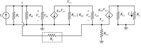
Figure 2
Mark the values and draw the PSpice circuit for the above circuit.
The required circuit is shown in Figure 3
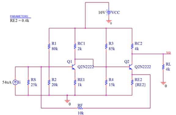
Figure 3
The snip for the drop box of the internal parameters of the transistor is shown in Figure 4
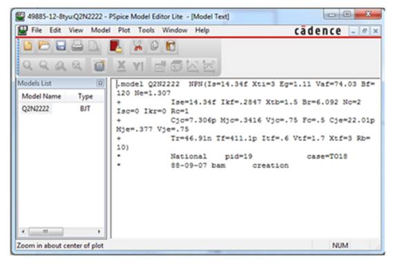
Figure 4
The simulation settings to estimate the magnitude of the current gain as the value of
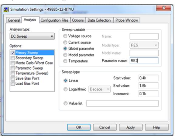
Figure 5
Then left click on the trace option then select add trace and type “ABS(l(RL)L(li))” then command in the trace magnitude of the current gain as the emitter resistance varies between
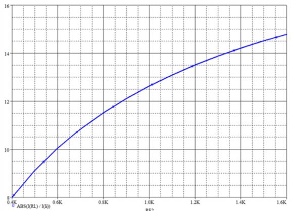
Figure 6
By KCL the expression for the current
The expression for the node voltage is given by,
Apply KCL at node
Substitute
The expression for the output current is given by,
Apply KCL at node
Substitute
Substitute
Consider
Thus, the expression for the small signal current gain is,
Conclusion:
Therefore, the relation between the current gain with the change in resistance
Want to see more full solutions like this?
Chapter 12 Solutions
MICROELECT. CIRCUIT ANALYSIS&DESIGN (LL)


- Identify the feedback system topology of the amplifier circuit as shown in Figure 4. Determine: V. the open loop gain, A = Vi i. Vf ii. the feedback gain, B Vo Vo iii. the gain with feedback, Af Vs iv. the expression of A, for Aß » 1 Vdd Rd + R2 Vo Vf R1 +arrow_forwardhow to find the closed loop poles and zeros on a tf like this by hand. With unity feedback.arrow_forwardQ-3: A- (a) The closed-loop gain of a negative-feedback amplifier is AfB the open-loop gain is A =-105. Find the feedback transfer function B. (b) If ß = -0.015 and A = -5 x 10⁴, determine the closed-loop gain AFB . -80 and 1:C:arrow_forward
- Q-3: A- (a) The closed-loop gain of a negative-feedback amplifier is AFg = -80 and the open-loop gain is A =-105. Find the feedback transfer function B. (b) If ß = -0.015 and A =-5 x 10*, determine the closed-loop gain AFBarrow_forwardFind the expression for the open loop gain Rm (=Output voltage/Input current). Get the expression for Ro,cl (closed loop output resistance).arrow_forward8. For the collector feedback configuration, determine : +16 V (a IB (b) Ic () Vc 3.6 kQ 470 k2 Vc IB B = 120 0.51 k2arrow_forward
- Compared to circuit without feedback, the output impedance in current shunt circuit is A.unpredictable B.not related at all C.similar D.larger E.dependiing on frequency F.smallerarrow_forwardWhat is an A/D converter with Voltage-to-Frequency Conversion (VFC)? What is the working principle?arrow_forwarda) An operational amplifier with non-inverting voltage feedback is given in Figure Q4.a. It has the following properties: Vin + 1 kQ Figure Q4.a Open loop gain: 100,000 Open loop output impedance: 400 Open loop bandwidth: 10 Hz Calculate: 1) The closed-loop voltage gain 2) The closed-loop output impedance 3) The closed-loop bandwidth Vout 99 ΚΩ R₁arrow_forward
- Q2) Consider the following feedback system outlined in Figure Q2 Plant R(s) + 10 1 C(s) S+ 1 K, Figure Q2 a) Derive the closed loop transfer function GRC (S). b} Calculate the value of Ky that will result in the closed loop system to have a maximum overshoot of 35% and a peak time of approximately 1 second. c) For the following systems assume zero initial conditions. Determine i) The peak overshoots. ii) Corresponding peak times iii) Decay rate characteristics. Produce a sketch of the unit step response using the above values calculated.arrow_forwardidentify the following 1. It characterizes the feedback system stability and transient properties.2. Is the product of the transfer functions of all branches that form the loop.3. Form of blocks in series that can be algebraically combined by multiplication of transfer functions.arrow_forward4- When a feedback voltage produces an increase in impedance, it is an example of......... a. Impedance compensation. c. Gain suppression. b. Shunt negative feedback. d. Series negative feedbackarrow_forward
 Introductory Circuit Analysis (13th Edition)Electrical EngineeringISBN:9780133923605Author:Robert L. BoylestadPublisher:PEARSON
 Delmar's Standard Textbook Of ElectricityElectrical EngineeringISBN:9781337900348Author:Stephen L. HermanPublisher:Cengage Learning
 Programmable Logic ControllersElectrical EngineeringISBN:9780073373843Author:Frank D. PetruzellaPublisher:McGraw-Hill Education
 Fundamentals of Electric CircuitsElectrical EngineeringISBN:9780078028229Author:Charles K Alexander, Matthew SadikuPublisher:McGraw-Hill Education
 Electric Circuits. (11th Edition)Electrical EngineeringISBN:9780134746968Author:James W. Nilsson, Susan RiedelPublisher:PEARSON
 Engineering ElectromagneticsElectrical EngineeringISBN:9780078028151Author:Hayt, William H. (william Hart), Jr, BUCK, John A.Publisher:Mcgraw-hill Education,