
Mechanics of Materials (MindTap Course List)
9th Edition
ISBN: 9781337093347
Author: Barry J. Goodno, James M. Gere
Publisher: Cengage Learning
expand_more
expand_more
format_list_bulleted
Concept explainers
Videos
Textbook Question
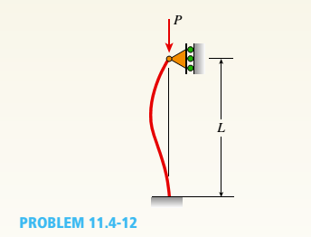
Chapter 11, Problem 11.4.12P
A fixed-pinned column is a W310 × 21 steel shape and is designed to carry an axial load of 125 kN. Determine the maximum permissible height L of the column if a factor of safety n = 2.5 is required with respect to the buckling of the column. Use E = 205 GPa and assume that the proportional limit is 340 MPa. The column may buckle about either axis of the cross section.
Expert Solution & Answer
Want to see the full answer?
Check out a sample textbook solution
Students have asked these similar questions
An
aluminum alloy tube with an outside diameter of 3.1 in. and a wall thickness of 0.36 in. is used as a 16-ft-long column. Assume that E
= 9300 ksi and that pinned connections are used at each end of the column. Determine the slenderness ratio L/r and the Euler buckling
load Per for the column.
Answers:
L/r=
Por=
kips
Q#3. An aluminium strut 16 ft long has a rectangular cross section 2 in by 3.5 in. A bolt through each end secure the strut in such a way that is acts as hinged column about an axis perpendicular to 3.5 in dimension; and as fixed column about an axis perpendicular to 2 in dimension. Determine the safe central load with a factor of safety of 2 and E= 10300000 psi.
Also discuss in detail about the governing column capacity and reasons behind it.
Two metal bars are fastened together at the
bolted flange connection shown. There are 2
total bolts connecting the two metal bars
together and each bolt has diameter
dbolt
12.7 mm. The flange is oriented at
angle = 50° with respect to longitudinal axis
of the metal bars. If an axial force F = 30 kN
is applied as shown, determine the overall
safety factor of the bolted connection. You
may assume the bolts are made out of
1020HR steel and the strength of the bolt in
shear is 50% of the tensile strength of the bolt
material.
F
-
SF overall =
0
number (rtol=0.01, at
F
?
Chapter 11 Solutions
Mechanics of Materials (MindTap Course List)
Ch. 11 - A rigid bar of length L is supported by a linear...Ch. 11 - The figure shows an idealized structure consisting...Ch. 11 - -2-3. Two rigid bars are connected with a...Ch. 11 - Repeat Problem 11.2-3 assuming that R= 10 kN ·...Ch. 11 - The figure shows an idealized structure consisting...Ch. 11 - An idealized column consists of rigid bar ABCD...Ch. 11 - An idealized column is made up of rigid segments...Ch. 11 - The figure shows an idealized structure consisting...Ch. 11 - The figure shows an idealized structure consisting...Ch. 11 - The figure shows an idealized structure consisting...
Ch. 11 - The figure shows an idealized structure consisting...Ch. 11 - Rigid column ABCD has an elastic support at B with...Ch. 11 - An idealized column is made up of rigid bars ABC...Ch. 11 - An idealized column is composed of rigid bars ABC...Ch. 11 - Repeat Problem 11.2-14 using L = 12 ft, ß = 0.25...Ch. 11 - An idealized column is composed of rigid bars ABC...Ch. 11 - Column AB has a pin support at A,a roller support...Ch. 11 - Slender column ABC is supported at A and C and is...Ch. 11 - Calculate the critical load PCTfor a W 8 × 35...Ch. 11 - Solve the preceding problem for a W 250 × 89 steel...Ch. 11 - Solve Problem 11.3-3 for a W 10 × 45 steel column...Ch. 11 - A horizontal beam AB is pin-supported at end A and...Ch. 11 - A column ABC is supported at ends A and C and...Ch. 11 - Find the controlling buckling load (kN) for the...Ch. 11 - A column, pinned at top and bottom, is made up of...Ch. 11 - Repeat Problem 11.3-9. Use two C 150 × 12.2 steel...Ch. 11 - A horizontal beam AB is pin-supported at end A and...Ch. 11 - -12 A horizontal beam AB is supported at end A and...Ch. 11 - A horizontal beam AB has a sliding support at end...Ch. 11 - A slender bar AB with pinned ends and length L is...Ch. 11 - A rectangular column with cross-sectional...Ch. 11 - .16 Three identical, solid circular rods, each of...Ch. 11 - Three pinned-end columns of the same material have...Ch. 11 - A long slender column ABC is pinned at ends A and...Ch. 11 - The roof over a concourse at an airport is...Ch. 11 - The hoisting arrangement for lifting a large pipe...Ch. 11 - A pinned-end strut of aluminum (E = 10,400 ksi)...Ch. 11 - The cross section of a column built up of two...Ch. 11 - The truss ABC shown in the figure supports a...Ch. 11 - A truss ABC supports a load W at joint B, as shown...Ch. 11 - An S6 × 12.5 steel cantilever beam AB is supported...Ch. 11 - The plane truss shown in the figure supports...Ch. 11 - A space truss is restrained at joints O, A,B, and...Ch. 11 - A fixed-end column with circular cross section is...Ch. 11 - A cantilever aluminum column has a square tube...Ch. 11 - An aluminum pipe column (E = 10,400 ksi) with a...Ch. 11 - Solve the preceding problem for a steel pipe...Ch. 11 - A wide-flange steel column (E = 30 × l06 psi) of...Ch. 11 - Prob. 11.4.6PCh. 11 - The upper end of a WE × 21 wide-flange steel...Ch. 11 - A vertical post AB is embedded in a concrete...Ch. 11 - The horizontal beam ABC shown in the figure is...Ch. 11 - The roof beams of a warehouse are supported by...Ch. 11 - Determine the critical load Pcrand the equation of...Ch. 11 - A fixed-pinned column is a W310 × 21 steel shape...Ch. 11 - Find the Controlling buckling load (kips) for the...Ch. 11 - Prob. 11.4.14PCh. 11 - A rigid L-shaped frame is supported by a steel...Ch. 11 - An aluminum tube AB with a circular cross section...Ch. 11 - The frame ABC consists of two members AB and BC...Ch. 11 - An aluminum bar having a rectangular cross section...Ch. 11 - ‘11.5-2 A steel bar having a square cross section...Ch. 11 - A simply supported slender column is subjected to...Ch. 11 - A brass bar of a length L = 0.4 m is loaded at end...Ch. 11 - Determine the bending moment M in the pinned-end...Ch. 11 - Plot the load-deflection diagram for a pinned-end...Ch. 11 - Solve the preceding problem for a column with e =...Ch. 11 - A wide-flange member (W200 × 22.5) is compressed...Ch. 11 - A wide-f hinge member (W 10 × 30) is compressed by...Ch. 11 - Solve the preceding problem (W 250 × 44.8) if the...Ch. 11 - The column shown in the figure is fixed at the...Ch. 11 - An aluminum box column with a square cross section...Ch. 11 - Solve the preceding problem for an aluminum column...Ch. 11 - A steel post /t if with a hollow circular cross...Ch. 11 - A frame ABCD is constructed of steel wide-flange...Ch. 11 - A steel bar has a square cross section of width b...Ch. 11 - ]11.6-2 A brass bar (E = 100 GPa) with a square...Ch. 11 - A square aluminum bar with pinned ends carries a...Ch. 11 - A pinned-and column of a length L = 2A m is...Ch. 11 - A pinned-end strut of a length L = 5.2 ft is...Ch. 11 - A circular aluminum tube with pinned ends supports...Ch. 11 - A steel W 12 × 35 column is pin-supported at the...Ch. 11 - A steel W 310 x 52 column is pin-supported at the...Ch. 11 - A steel column (E = 30 x 103 ksi) with pinned ends...Ch. 11 - A W410 × S5 steel column is compressed by a force...Ch. 11 - A steel column ( E = 30 X 103 ksi) that is fixed...Ch. 11 - AW310 × 74 wide-flange steel column with length L...Ch. 11 - A pinned-end column with a length L = 18 ft is...Ch. 11 - The wide-flange, pinned-end column shown in the...Ch. 11 - A W14 × 53 wide-flange column of a length L = 15...Ch. 11 - A wide-flange column with a bracket is fixed at...Ch. 11 - Determine the allowable axial load Pallowa W 10 X...Ch. 11 - Determine the allowable axial load Pallowfor a W...Ch. 11 - Determine the allowable axial load Pallowfor a W...Ch. 11 - Select a steel wide-flange column of a nominal...Ch. 11 - Prob. 11.9.5PCh. 11 - Select a steel wide-flange column of a nominal...Ch. 11 - Prob. 11.9.7PCh. 11 - Determine the allowable axial load Pallowfor a...Ch. 11 - Determine the allowable axial load Pallowfor a...Ch. 11 - Determine the allowable axial load Pallowfor a...Ch. 11 - -11 Determine the maximum permissible length...Ch. 11 - Determine the maximum permissible length Lmaxfor a...Ch. 11 - A steel pipe column with pinned ends supports an...Ch. 11 - The steel columns used in a college recreation...Ch. 11 - A W8 × 28 steel wide-flange column with pinned...Ch. 11 - Prob. 11.9.16PCh. 11 - Prob. 11.9.17PCh. 11 - Prob. 11.9.18PCh. 11 - Prob. 11.9.19PCh. 11 - Prob. 11.9.20PCh. 11 - Prob. 11.9.21PCh. 11 - An aluminum pipe column (alloy 2014-T6) with...Ch. 11 - Prob. 11.9.23PCh. 11 - Prob. 11.9.24PCh. 11 - Prob. 11.9.25PCh. 11 - Prob. 11.9.26PCh. 11 - Prob. 11.9.27PCh. 11 - Prob. 11.9.28PCh. 11 - Prob. 11.9.29PCh. 11 - Prob. 11.9.30PCh. 11 - A wood column with, a rectangular cross section...Ch. 11 - Prob. 11.9.32PCh. 11 - Prob. 11.9.33PCh. 11 - A square wood column with side dimensions b (see...Ch. 11 - A square wood column with side dimensions b (see...Ch. 11 - Prob. 11.9.36P
Knowledge Booster


Learn more about
Need a deep-dive on the concept behind this application? Look no further. Learn more about this topic, mechanical-engineering and related others by exploring similar questions and additional content below.Similar questions
- 7 ft 5 ft The assembly shown above includes column AB, which has the following properties: Pinned (top and bottom) for buckling about x-axis Free at top and fixed at bottom for buckling about y-axis Circular cross-section with 8-inch diameter E = 10000 ksi Which of the following is closest to the critical buckling force of column AB? O Per = 269 kip O Per = 1080 kip O Per = 538 kip O Per = 135 kiparrow_forwardTwo metal bars are fastened together at the bolted flange connection shown. There are 4 total bolts connecting the two metal bars together and each bolt has diameter = 50° with dbolt 12.7 mm. The flange is oriented at angle respect to longitudinal axis of the metal bars. If an axial force F = 40 kN is applied as shown, determine the overall safety factor of the bolted connection. You may assume the bolts are made out of 1020HR steel and the strength of the bolt in shear is 50% of the tensile strength of the bolt material. = F SFO overall = Ө number (rtol=0.01, atol=1e-05) F ?arrow_forwardDetermine the critical axial buckling load for an 8 3/4 x 12 inches glue-laminated column braced at 10ft from the bottom in the y axis for a total height of 25ft. Assume pin connections at top and bottom. Fc= 1750 psi, E= 1.8x10⁶ psi. (Western cross-section glu-lam data is in the text).arrow_forward
- The pin-connected assembly consists of aluminum rods (1) and (2) and steel rod (3). The aluminum rods each have a diameter of 14 mm and an elastic modulus of E = 70 GPa. The steel rod has a diameter of 15 mm and an elastic modulus of E= 180 GPa. Assume a = 3.0 m, b = 1.6 m, and c = 1.0 m. What is the magnitude of load P that is necessary to displace point A 7mm to the left? A Answer: P = i (3) eTextbook and Media Save for Later B b D kN Attempts: 0 of 5 used Submit Answerarrow_forwardTwo metal bars are fastened together at the bolted flange connection shown. There are 2 total bolts 12.7 mm. The flange is - connecting the two metal bars together and each bolt has diameter dbolt oriented at angle 55° with respect to longitudinal axis of the metal bars. If an axial force F = 40 kN is applied as shown, determine the overall safety factor of the bolted connection. You may assume the bolts are made out of 1020HR steel and the strength of the bolt in shear is 50% of the tensile strength of the bolt material. SF overall F = = 2.576 Ꮎ ? X 0% = Farrow_forwardThe pin-connected assembly consists of aluminum rods (1) and (2) and steel rod (3). The aluminum rods each have a diameter of 14 mm and an elastic modulus of E = 70 GPa. The steel rod has a diameter of 15 mm and an elastic modulus of E= 180 GPa. Assume a = 3.0 m, b = 1.6 m, and c = 1.0 m. What is the magnitude of load P that is necessary to displace point A 7 mm to the left? A Answer: P = i (3) eTextbook and Media Save for Later B b D kN Attempts: 0 of 5 used Submit Answerarrow_forward
- The pin-connected assembly consists of aluminum rods (1) and (2) and steel rod (3). The aluminum rods each have a diameter of 18 mm and an elastic modulus of E = 71 GPa. The steel rod has a diameter of 16 mm and an elastic modulus of E = 200 GPa. Assume a = 3.5 m, b = 1.4 m, and c = 1.1 m. What is the magnitude of load P that is necessary to displace point A 13 mm to the left? B Answer: P = i KNarrow_forwardA spreader bar is used in the assembly shown in the figure attached. It is made of a circular steel ros of diameter 32mm. Assuming that the cables and their connections are inextensible, determine largest load W that can be applied so that the spreader bar does not buckle. Both end of the spreader bar may be assumed to be pin connected. The youngs modulus of the spreader bar is, E = 200 x 10^3 N/mm^2.arrow_forward2. In the following truss structure, the angles of A and B are 6A = 120° and 0,= 30°, respectively. Determine the diameter size of the rods AB, BC and CD if oy = 2400 MPa and the safety factor SF = 2. Assume the rods are solid cyllinders. 50 kN 100 KN 2 m Barrow_forward
- 5. Determine the greatest load P the frame will support without causing the A-36 steel member BC to buckle. Due to the forked ends on the member, consider the supports at B and C to act as pins for x-x axis buckling and as fixed supports for y-y axis buckling. Given E = 200 Gpa. -1.2 m- -1.2 m- 0.9 m 75 mm 25 mm Figure 5arrow_forwardProblem 3 The truss shown below consists of aluminum (E = 10,000 ksi) members that are pin connected together, and each member has a solid circular cross section. Member BC of the truss is loaded in compression and must be designed to resist buckling. Determine the minimum radius of member BC to prevent Euler buckling with a factor of safety of 2. Let P1 = 800 lb, P2 = 600 lb and a = 8 ft. %3D !3! B. P2arrow_forwardThe horizontal link BC is 6.35 mm thick, has a width w = 31.8 mm, and is made of steel with ultimate tensile strength equal to 483 MPa. What should be the factor of safety to be used if the structure shown is designed to support a load P = 44.5 kN.arrow_forward
arrow_back_ios
SEE MORE QUESTIONS
arrow_forward_ios
Recommended textbooks for you
 Mechanics of Materials (MindTap Course List)Mechanical EngineeringISBN:9781337093347Author:Barry J. Goodno, James M. GerePublisher:Cengage Learning
Mechanics of Materials (MindTap Course List)
Mechanical Engineering
ISBN:9781337093347
Author:Barry J. Goodno, James M. Gere
Publisher:Cengage Learning
Column buckling; Author: Amber Book;https://www.youtube.com/watch?v=AvvaCi_Nn94;License: Standard Youtube License