
Concept explainers
Videos
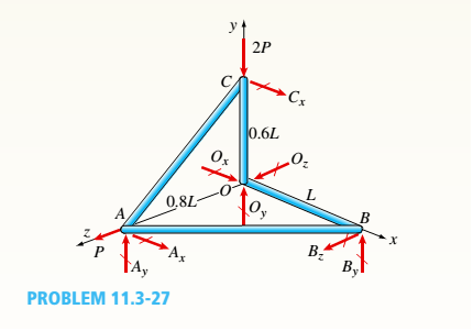
A space truss is restrained at joints O, A,B, and C as shown in the figure. Load F is applied at joint A and load 2F acts downward at joint C. Each member is a slender, circular pipe (E = 10,600 ksi) with an outside diameter of 3.5 in. and wall thickness of 0.25 in. Length variable L = 11 ft. Determine the critical value of load variable P (kips) at which member OB fails by Euler buckling.
The critical value of load
Answer to Problem 11.3.27P
The critical value of load
Explanation of Solution
Given information:
Young’s modulus of each member is
Write the expression for force equilibrium at joint
Here, force generated in member
Write the expression for force equilibrium at joint
Here, force generated in member
Write the expression for force equilibrium at joint
Here, the reaction force in
Write the expression for moment equilibrium equation at point
Here, the length variable of the truss is
Substitute
Write the expression for moment equilibrium equation at point
Here, reaction force in
Write the expression for moment equilibrium equation at point
Here, reaction force in
Substitute
The figure below shows the free body diagram of joint
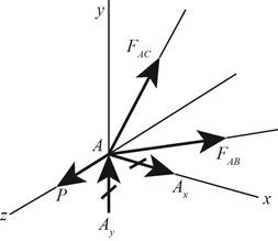
Figure-(1)
Write the expression for force equilibrium at joint
Here, the force generated in member
Write the expression for the angle between member
Substitute
Write the expression for force in member
Substitute
Write the expression for moment of inertia for circular pipe.
Here, outer diameter of circular pipe is
Write the expression for inner diameter of circular pipe.
Here, the wall thickness of the circular pipe is
Write the expression for critical load in member
Here, the young’s modulus of members is
Substitute
Substitute
Calculation:
Substitute
Substitute
Substitute
Conclusion:
The critical value of load
Want to see more full solutions like this?
Chapter 11 Solutions
Mechanics of Materials (MindTap Course List)


- The truss ABC shown in the figure supports a vertical load W at joint B. Each member is a slender circular steel pipe (E = 30,000 ksi) with an outside diameter of 4 in. and wall thickness 0.25 in. The distance between supports is 23 ft. Joint B is restrained against displacement perpendicular to the plane of the truss. Determine the critical value Wcr of the load.arrow_forwardA sign for an automobile service station is supported by two aluminum poles of hollow circular cross section, as shown in the figure. The poles are being designed to resist a wind pressure of 75 lb/ft" against the full area of the sign. The dimensions of the poles and sign are hx= 20 ft, /r =5 ft, and h = 10 ft. To prevent buckling of the walls of the poles, the thickness e is specified as one-tenth the outside diameter d. (a) Determine the minimum required diameter of the poles based upon an allowable bending stress of 7500 psi in the aluminum. (b) Determine the minimum required diameter based upon an allowable shear stress of 300 psi.arrow_forwardA steel post (E=30×106) having thickness t = 1/8 in. and height L = 72 in. support a stop sign (see figure), where s = 12.5 in. The height of the post L is measured from the base to the centroid of the sign. The stop sign is subjected to wind pressure p = 20 lb/ft2 normal to its surface. Assume that the post is fixed at its base. What is the resultant load on the sign? (Sec Appendix E, Case 25, for properties of an octagon, n =8.) What is the maximum bending stress in the post? Repeat part (b) if the circular cut-outs arc eliminated over the height of the post.arrow_forward
- A hollow circular tube T of a length L = 15 in. is uniformly compressed by a force P acting through a rigid plate (see figure). The outside and inside diameters of the tube are 3.0 and 2.75 in., respectively. A concentric solid circular bar B of 1.5 in. diameter is mounted inside the lube. When no load is present, there is a clearance c = 0.0I0 in. between the bar B and the rigid plate. Both bar and tube are made of steel having an c[autoplastic stress-strain diagram with E = 29 X LO3 ksi and err= 36 ksi. (a) Determine the yield load Pt- and the corresponding shortening 3yof the lube. (b) Determine the plastic load Ppand the corresponding shortening Spof the tube. (c) Construct a load-displacement diagram showing the load Pas ordinate and the shortening 5 of the tube as abscissa. Hint: The load-displacement diagram is not a single straight line in the region 0 ^ P ^ Prarrow_forwardA long, rectangular copper bar under a tensile load P hangs from a pin that is supported by two steel posts (see figure). The copper bar has a length of 2.0 m, a cross-sectional area of4S00 mm", and a modulus of elasticity Ec= 120 GPa. Each steel post has a height of 0.5 m, a cross-sectional area of 4500 mm2, and a modulus of elasticity E = 200 GRa. (a) Determine the downward displacementarrow_forwardThe plane truss shown in the figure supports vertical loads F at joint D, 2F at joint C, and 3F at joint B. Each member is a slender circular pipe (E = 70 GPa) with an outside diameter of 60 mm and wall thickness of 5 mm. Joint B is restrained against displacement perpendicular to the plane of the truss. Determine the critical value of load variable F(kN) at which member BF fails by Eu1er buckling.arrow_forward
- -21 Plastic bar AB of rectangular cross section (6 = 0.75 in. and h = 1.5 in.) and length L = 2 Ft is Fixed at A and has a spring support (Ar = 18 kips/in.) at C (see figure). Initially, the bar and spring have no stress. When the temperature of the bar is raised hy foot. the compressive stress on an inclined plane pq at Lq = 1.5 Ft becomes 950 psi. Assume the spring is massless and is unaffected by the temperature change. Let a = 55 × l0-6p and E = 400 ksi. (a) What is the shear stresst9 on plane pq? What is angle 07 =1 Draw a stress element oriented to plane pq, and show the stresses acting on all laces of this element. (c) If the allowable normal stress is ± 1000 psi and the allowable shear stress is ±560 psi, what is the maximum permissible value of spring constant k if the allowable stress values in the bar are not to be exceeded? (d) What is the maximum permissible length L of the bar if the allowable stress values in the bar are not be exceeded? (Assume £ = IB kips/in.) (e) What is the maximum permissible temperature increase (A7") in the bar if the allowable stress values in the bar are not to be exceeded? (Assume L = 2 ft and k = L& kips/inarrow_forwardTwo pipe columns (AB, FC) are pin-connected to a rigid beam (BCD), as shown in the figure. Each pipe column has a modulus of E, but heights (L1or L2) and outer diameters (d1or different for each column. Assume the inner diameter of each column is 3/4 of outer diameter. Uniformly distributed downward load q = 2PIL is applied over a distance of 3L/4 along BC, and concentrated load PIA is applied downward at D. (a) Derive a formula for the displacementarrow_forwardA rigid triangular frame is pivoted at C and held by two identical horizontal wires at points A and B (see figure). Each wire has an axial rigidity EA = 120 kips and coefficient of thermal expansion a = 12.5 X 10⁻⁶/°F. (a) If a vertical load P = 500 lb acts at point D, what are the tensile forces TAand TBin the wires at A and B, respectively? (b) If both wires have their temperatures raised by 180°F while the load P is acting, what are the forces TAand TB (c) What further increase in temperature will cause the wire at B to become slack?arrow_forward
- The roof over a concourse at an airport is supported by the use of pretensioned cables. At a typical joint in the roof structure, a strut AB is compressed by the action of tensile forces Fin a cable that makes an angle = 75° with the strut (see figure and photo). The strut is a circular tube of steel (E = 30,000 ksi) with outer diameter d2= 2.5 in. and inner diameter d1= 2.0 in. The strut is 5.75 ft long and is assumed to be pin-connected at both ends. Using a factor of safety n = 2.5 with respect to the critical load, determine the allowable force F in the cable.arrow_forwardThe horizontal beam ABC shown in the figure is supported by columns BD and CE. The beam is prevented from moving horizontally by the pin support at end A. Each column is pinned at its upper end to the beam, but at the lower ends, support D is a sliding support and support E is pinned. Both co lu in us arc solid steel bars (E = 30 × 106 psi) of square cross section with width equal to 0.625 in. A load Q acts at distance a from column BD. If the distance a = 12 in., what is the critical value Qcr of the load? If the distance a can be varied between 0 and 40 in., what is the maximum possible value of Qcr? What is the corresponding value of the distance a?arrow_forwardA long slender column ABC is pinned at ends A and C and compressed by an axial force F (sec figure). At the midpoint B, lateral support is provided to prevent deflection in the plane of the figure. The column is a steel wide-flange section (W 250 × 67) with E = 200 GPa. The distance between lateral supports is L = 5.5 m. Calculate the allowable load P using a factor of safety n = 2.4, taking into account the possibility of Eu 1er buckling about cither principal centroidal axis (i.e., axis 1-1 or axis 2-2).arrow_forward
 Mechanics of Materials (MindTap Course List)Mechanical EngineeringISBN:9781337093347Author:Barry J. Goodno, James M. GerePublisher:Cengage Learning