
Videos
The schematic of a single-flash geothermal power plant with state numbers is given in Fig. P10–69. Geothermal resource exists as saturated liquid at 230°C. The geothermal liquid is withdrawn from the production well at a rate of 230 kg/s and is flashed to a pressure of 500 kPa by an essentially isenthalpic flashing process where the resulting vapor is separated from the liquid in a separator and is directed to the turbine. The steam leaves the turbine at 10 kPa with a moisture content of 5 percent and enters the condenser where it is condensed; it is routed to a reinjection well along with the liquid coming off the separator. Determine (a) the power output of the turbine and the thermal efficiency of the plant, (b) the exergy of the geothermal liquid at the exit of the flash chamber, and the exergy destructions and the second-law efficiencies for (c) the turbine and (d) the entire plant.
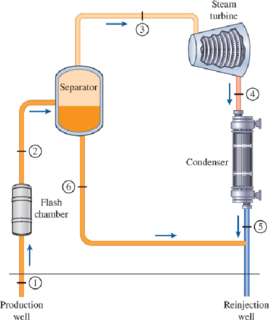
FIGURE P10–69
(a)
The temperature of the steam after the flashing process and the power output from the turbine if the pressure of the steam at the exit of flash chamber is
Answer to Problem 69P
The power output turbine is
The thermal efficiency of the plant is
Explanation of Solution
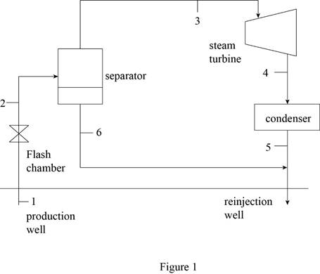
Draw schematic diagram of single flash geothermal power plant as shown in Figure 1.
Write the general energy rate balance equation.
Here, the rate of total energy in is
Consider the system operates at steady state. Hence, the rate of change in net energy of the system becomes zero.
The Equation (I) is reduced as follows.
Refer Figure 1.
The flash chamber is nothing but the expansion valve. At expansion valve, the enthalpy kept constant.
Express the energy balance equation for the flash chamber.
Express the energy balance equation for the separator.
Express the energy balance equation for the turbine.
At state 1:
The geothermal water is extracted at the state of saturated liquid at the temperature of
The enthalpy and entropy at state 1 is as follows.
Refer Table A-4, “Saturated water-Temperature table”
The enthalpy
Refer Table A-1, “Molar mass, gas constant, and critical-point properties”.
At state 2:
The exit pressure of the flash chamber is
The geothermal steam is flashed at constant enthalpy. The exit steam of the flash chamber is at the quality of
Here, the fluid enthalpy is
Refer Table A-5, “Saturated water-Pressure table”.
Obtain the following corresponding to the pressure of
The entropy
Write the formula for mass flow rate of vapor at entering the turbine.
Here, the mass flow rate is
At state 3:
There is no pressure drop in the separator. The separator separates vapor and liquid form the flashed steam, and the separated vapor alone sent to the turbine.
The enthalpy
Refer Table A-5, “Saturated water-Pressure table”.
The enthalpy
At state 4:
The steam is at the state of saturated mixture at the pressure of
The quality at state 4 is as follows.
The enthalpy
Refer Table A-5, “Saturated water-Pressure table”.
Obtain the following corresponding to the pressure of
At state 6:
The saturated water only exits at the bottom of the separator. The enthalpy
Refer Table A-5, “Saturated water-Pressure table”.
The enthalpy
Write the formula for net energy input of the plant.
Write the formula for thermal efficiency.
Consider, the surrounding temperature is
The surrounding enthalpy
Refer Table A-4, “Saturated water-Temperature table”.
The enthalpy
Conclusion:
Substitute
Substitute
Substitute
Substitute
Equation (VII).
Substitute
Substitute
Equation (III).
Thus, the power output turbine is
Substitute
Equation (IX).
Substitute
Thus, the thermal efficiency of the plant is
(b)
The exergy of the geothermal liquid at the exit of the flash chamber, and the exergy destructions.
Answer to Problem 69P
The exergy of the geothermal liquid at the exit of the flash chamber, and the exergy destruction is
Explanation of Solution
Write the formula for exergy of the steam at their respective process state.
Here, the enthalpy is
Write the formula for rate of exergy destruction at the exit of flash chamber (state 6).
Here, the rate of exergy destruction at state 6 is
Conclusion:
For process state 1:
Substitute
For process state 2:
Substitute
For process state 3:
Substitute
For process state 4:
Substitute
For process state 6:
Substitute
The mass flow rate of water at the bottom exit of separator (state 6) is expressed as follows.
Substitute
Thus, the exergy of the geothermal liquid at the exit of the flash chamber, and the exergy destruction is
(c)
The exergy destruction and second law of efficiency for the turbine.
Answer to Problem 69P
The exergy destruction and second law of efficiency for the turbine is
Explanation of Solution
Write the formula for rate of exergy destruction of the turbine.
Write the formula for second law of efficiency of the turbine.
Conclusion:
Substitute
Substitute
Thus, the exergy destruction and second law of efficiency for the turbine is
(d)
The exergy destruction and second law of efficiency for the entire plant.
Answer to Problem 69P
The exergy destruction and second law of efficiency for the plant is
Explanation of Solution
Write the formula for rate of exergy input of the plant.
Write the formula for rate of exergy destruction of the plant.
Write the formula for second law of efficiency of the plant.
Conclusion:
Substitute
Substitute
Substitute
Thus, the exergy destruction and second law of efficiency for the plant is
Want to see more full solutions like this?
Chapter 10 Solutions
Thermodynamics: An Engineering Approach


- 3. The schematic of a single-flash geothermal power plant with state numbers is given in the fiure below. Geothermal resource exists as saturated liquid at 230°C. The geothermal liquid is withdrawn from the production well at a rate of 230 kg/s and is flashed to a pressure of 500 kPa by an essentially isenthalpic flashing process where the resulting vapor is separated from the liquid in a separator and is directed to the turbine. The steam leaves the turbine at 10 kPa with a moisture content of 5 percent and enters the condenser where it is condensed; it is routed to a reinjection well along with the liquid coming off the separator. Determine (a) the power output of the turbine and the thermal efficiency of the plant, Answers: (a) 10.8 MW, 0.053, Separator Flash chamber Production well Steam turbine Condenser Ⓒ-1 Reinjection wellarrow_forwardSteam is generated at 5.15 Mpa and 525C and condensation occurs at 0.127 Mpa. Considering that a Rankine cycle occurs between the same limits, determine the QA, QR, Wnet, cycle efficiency, engine efficiency and heat rate. What mass flow rate is required for a net output of 25000 kW?arrow_forwardThe production well of a typical geothermal power plant is at 230°C saturated liquid and ground water flow rate of 230kg/s with separator pressure of 0.5MPaa while its condenser pressure is at 0.01MPa. the turbine and generator efficiencies are 83% and 87% , respectively. Sketch the T-s diagram of the system. Determine the amount of mass flowing into the reinjection well from the separator, generator output, heat rejection in the condenser and overall plant efficiency.arrow_forward
- A medium size power station is used to produce 30 MW net power for a refinery. The station uses steam as the operating fluid and operates according to the Carnot cycle between the pressure limits of 0.4 bar and 35 bar. Steam enters the boiler as a saturated liquid and leaves it as a dry saturated vapour. ist t Reneric o "nd h Ts diaar ntion of s) (ii) Determine the dryness fraction of the steam that is fed to the condenser. (4 marks) (iv) Determine the specific enthalpy values at the four key points of the cycle. (6 marks) Calculat "Fic of the cycle (5 Ma, KS) (vi) Determine the thermal efficiency of the cycle. (1 mark) (vii) Using the highest and lowest temperature values in the cycle, re- calculate the efficiency of the cycle and show that it is equivalent to the result in part (vi). (2 marks) arks). 2.arrow_forwardA power station consists of a four-unit coal fired power station, having a combined capacity of 2,880 MW. The current efficiency of each unit is around 37.7%. You are asked to improve the thermal efficiency of each unit by lowering the condenser pressure. To simplify this task, assume that each unit operates on a simple ideal Rankine cycle. If the superheated vapour enters the turbine at 10 MPa and 500 ֯C and is cooled in the condenser at a lower pressure 10 kPa, determine the quality of the steam at the turbine exit and the thermal efficiency of the cycle for one unit.arrow_forwardThe following image describe a single-flash geothermal power plant. We have the follow informations about the system: The flash chamber (throttling valve) is a isenthalpic device The system is adiabatic The power generated by the turbine is 10kW The pressure and temperature at point 4 are 50 kPa and 100°C respectively The pressure at separator is 500 kPa The separator has the function of separating the phases of a saturated mixture The mass that exits the system through the separator is 5 times the mass that exits the turbine. The pressure at point 1 is 1 MPa If all the information is sufficient, fill in the table below and plot all the points on a T x v graph.arrow_forward
- In a steam power plant, the condenser pressure is 10 kPa. The turbine and pump isentropic efficiencies are both 85 %. Draw the schematic and T-S diagrams. Label the points by setting point 1 at the condenser outlet, point 2 at the pump outlet, point 3 at the boiler outlet, and point 4 at the turbine outlet. Use the label 2a and 4a for the points due to the isentropic efficiency of the pump and turbine, respectively. Use 2 decimal places for the enthalpy and other energies in solving and for the final answers. For the steam quality (x) and entropy (s), use 4 decimal places in solving. For the specific volume, use 6 decimal places. The pressure and the temperature of steam that enters the turbine are 4 MPa and 700 oC Determine the following: (INPUT YOUR ANSWERS ON THE BLANK SPACES PROVIDED.) Enthalpy at point 1 in kJ/kg = Enthalpy at point 2 in kJ/kg = Enthalpy at point 3 in kJ/kg = Enthalpy at point 4 in kJ/kg = Actual Enthalpy at point 2a in kJ/kg = Actual Enthalpy at point 4a…arrow_forwardIn a steam power plant, the condenser pressure is 10 kPa. The turbine and pump isentropic efficiencies are both 85 %. Draw the schematic and T-S diagrams. Label the points by setting point 1 at the condenser outlet, point 2 at the pump outlet, point 3 at the boiler outlet, and point 4 at the turbine outlet. Use the label 2a and 4a for the points due to the isentropic efficiency of the pump and turbine, respectively. Use 2 decimal places for the enthalpy and other energies in solving and for the final answers. For the steam quality (x) and entropy (s), use 4 decimal places in solving. For the specific volume, use 6 decimal places. The pressure and the temperature of steam that enters the turbine are 4 MPa and 700 oC (use the given values assigned on your name in the table below) Determine the following: Enthalpy at point 1 in kJ/kg= Enthalpy at point 2 in kJ/kg = Enthalpy at point 3 in kJ/kg = Enthalpy at point 4 in kJ/kg = Actual Enthalpy at point 2a in kJ/kg= Actual Enthalpy at…arrow_forwardCondenser a steam power plant that operates on a simple ideal ranking cycle and has a net power output of 22MW. Steam enters the turbine at 7Mpa and 450.05°C and is cooled in the condenser at a pressure of 10kpa by running cooling water from a lake through the tubes of the condenser at rate of 1750 kg/s. Determine the mess flow rates of steam through the steam turbine assuming that the cp of superheated steam is 2.9593kJ/kg.K.arrow_forward
- A medium size power station is used to produce 30 MW net power for a refinery. The station uses steam as the operating fluid and operates according to the Carnot cycle between the pressure limits of 0.4 bar and 35 bar. Steam enters the boiler as a saturated liquid and leaves it as a dry saturated vapour. (iii) Determine the dryness fraction of the steam that is fed to the condenser. (iv) Determine the specific enthalpy values at the four key points of the cycle. (v) Calculate the specific heat provided to the boiler, the specific work extracted from the power station and the mass flow rate of the steam circulating in the cyclearrow_forward9. A steam generating plant consisting of a boiler, an economizer and super heater generates superheated steam at a rate of 50 metric tons per hour. The feedwater enters the boiler at 10.0 mpa and 100°C compressed liquid. The steam leaves the superheater at 10.0 pa pressure with a temperature of 1000°C. Calculate the volume of fuel to be burned in liters per hour for a boiler efficiency of 80%. The heating value of fuel is 10,000 Kcal/Kg. a) 7,344 liters/hr b.) 6,325 liters/hr c.) 5,832 liters/hr d.) 8,028 liters/hr Hide allarrow_forwardSteam enters the turbine of a cogeneration plant at 6 MPa and 550 degrees * C . One-third of the steam is extracted from the turbine at 1400 kPa pressure for process heating. The remaining steam continues to expand to 20 kPa. The extracted steam is then condensed and mixed with feedwater at constant pressure and the mixture is pumped to the boiler pressure of 6 MPaThe mass flow rate of steam through the boiler is 30 kg/s. Disregarding any pressure drops and heat losses in the piping, and assuming the turbine and the pump to be isentropic, determine (a) the net power produced(b) the utilization factor of the plant, (c) the exergy destruction associated with the process heating, and (d ) the entropy generation associated with the process in the boiler. Assuming a source temperature of 1000 K and a sink temperature of 298 Karrow_forward
 Principles of Heat Transfer (Activate Learning wi...Mechanical EngineeringISBN:9781305387102Author:Kreith, Frank; Manglik, Raj M.Publisher:Cengage Learning