
Videos
Reconsider Prob. 10–83. Determine which components of the combined cycle are the most wasteful of work potential.
10–83 A combined gas–steam power cycle uses a simple gas turbine for the topping cycle and simple Rankine cycle for the bottoming cycle. Atmospheric air enters the gas turbine at 101 kPa and 20°C, and the maximum gas cycle temperature is 1100°C. The compressor pressure ratio is 8; the compressor isentropic efficiency is 85 percent; and the gas turbine isentropic efficiency is 90 percent. The gas stream leaves the heat exchanger at the saturation temperature of the steam flowing through the heat exchanger. Steam flows through the heat exchanger with a pressure of 6000 kPa and leaves at 320°C. The steam-cycle condenser operates at 20 kPa, and the isentropic efficiency of the steam turbine is 90 percent. Determine the mass flow rate of air through the air compressor required for this system to produce 100 MW of power. Use constant specific heats for air at room temperature.
Which component of the combined cycle is the most wasteful of work potential.
Answer to Problem 85P
The combustor of the gas-steam cycle has largest exergy destruction
Explanation of Solution
Show the
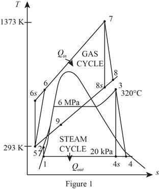
Refer Figure 1.
Consider the gas cycle (topping cycle) and their respective process states such as 5, 6,
Write the temperature and pressure relation at isentropic state and for the process 5-6-
Here, the temperature is
Write the formula for isentropic efficiency of compressor for the process 5-6-
Here, the enthalpy is
Rearrange and rewrite the equation (II) to obtain
Write the temperature and pressure relation at isentropic state and for the process 7-8-
Write the formula for isentropic efficiency of gas turbine
Rearrange and rewrite the equation (V) to obtain
At state 9: (heat exchanger)
The temperature
Refer Table A-5, “Saturated water-Pressure table”.
The saturation temperature corresponding to the pressure of
Refer Figure 1.
Consider the steam cycle (bottoming cycle) and their respective process states such as 1, 2, 3, 4,
At state 1:
The water exits the condenser as a saturated liquid at the pressure of
Refer Table A-5, “Saturated water-Pressure table”.
The enthalpy
At state 2:
Write the formula for work done by the pump during process 1-2.
Here, the specific volume is
Write the formula for enthalpy
At state 3: (Turbine inlet)
The steam enters the turbine as superheated vapour.
Refer Table A-6, “Superheated water”.
The enthalpy
From Figure 1,
At state 4: (Turbine exit or condenser inlet)
The steam exits the condenser as a saturated liquid at the pressure of
The quality of water at the exit of the turbine is expressed as follows.
The enthalpy at state
Here, the enthalpy is
Refer Table A-5, “Saturated water-Pressure table”.
Obtain the following properties corresponding to the pressure of
Write the formula for isentropic efficiency of the steam turbine
Rearrange the Equation (XI) to obtain the enthalpy
Write the formula for net work output of the gas cycle.
Here, the specific heat of air at constant pressure is
Write the formula for net work output of the steam cycle.
Write the general energy rate balance equation.
Here, the rate of energy in is
Consider the heat exchanger operates on steady state. Hence, the rate of change in net energy of the system is zero.
The Equation (XV) is reduced as follows for the heat exchanger.
Here, the mass flow rate of air is
Write the formula for mass flow rate of air through the compressor.
Write the formula for the exergy destruction for the process 3-4 (turbine).
Write the formula for the exergy destruction for the process 4-1 (condenser).
Write the formula for the exergy destruction for heat exchanger.
Write the formula for the exergy destruction for the process 5-6 (compressor).
Write the formula for the exergy destruction for the process 6-7 (combustion chamber).
Write the formula for the exergy destruction for the process 7-8 (gas turbine).
Here, the specific heat at constant pressure of air is
Refer Table A-2, “Ideal-gas specific heats of various common gases”.
The specific heat at constant pressure
Conclusion:
Substitute
Substitute
Substitute
Substitute
Substitute
Substitute
Here,
Substitute
Substitute
Equation (X).
Substitute
Substitute
Substitute
Equation (XIV).
Substitute
When, the mass flow rate of air is
Substitute
Thus, the Equation (XXIV) describes that
Substitute
Thus, the mass flow rate of the air through the air compressor required for this system to produce
Substitute
Consider the process 1 to 2 (Pump).
Here, the pump is isentropic. Hence the exergy destruction during the process 1-2 is zero.
Consider the process 3 to 4 (steam turbine).
Here,
Substitute
Thus, the exergy destruction during process 3-4 is
Substitute
Substitute
Substitute
Substitute
Substitute
The calculated exergy destruction value is greater for component combustor that is
Hence, the combustor of the gas-steam cycle has largest exergy destruction of all other components and that is the most wasteful of work potential.
Want to see more full solutions like this?
Chapter 10 Solutions
Thermodynamics: An Engineering Approach
Additional Engineering Textbook Solutions
Heating Ventilating and Air Conditioning: Analysis and Design
Fluid Mechanics: Fundamentals and Applications
Vector Mechanics for Engineers: Statics and Dynamics
Manufacturing Engineering & Technology
Engineering Mechanics: Statics
Statics and Mechanics of Materials


- A steam power plant operates on the ideal reheat Rankine cycle. Steam enters the high-pressure turbine at 7 MPa and 450°C and leaves at 2 MPa. Steam is then reheated at constant pressure to 450°C before it expands to 20 kPa in the low-pressure turbine. Determine the turbine work output, in kJ/kg, and the thermal efficiency of the cycle. Also, show the cycle on T-S diagram with respect to saturation lines.arrow_forwardRequired information. The net work output and the thermal efficiency for the Carnot and the simple ideal Rankine cycles with steam as the working fluid are to be calculated and compared. Steam enters the turbine in both cases at 10 MPa as a saturated vapor, and the condenser pressure is 50 kPa. In the Rankine cycle, the condenser exit state is saturated liquid and, in the Carnot cycle, the boiler inlet state is saturated liquid. Draw the T-s diagrams for both cycles. (Please upload your response/solution using the controls below.) upload a response file (15MB max) Choose File no file selected savearrow_forwardA steam power plant operates on the ideal reheat Rankine cycle. Steam enters the high pressure turbine at 8 MPa and 500 C and leaves at 3 MPa. Steam is then reheated at constant pressure to 500 C before it expands to 20 kPa in the low pressure turbine. Determine the turbine work output, in kJ/kg, and the thermal efficiency of the cycle. Also show the cycle on a T-s diagram with respect to the saturation lines.arrow_forward
- A combined gas-steam power cycle uses a simple gas turbine for the topping cycle and simple Rankine cycle for the bottoming cycle, Atmospheric air enters the gas turbine at 101 kPa and 20°C, and the maximum gas cycle temperature is 1100°C. The compressor pressure ratio is 8, the compressor isentropic efficiency is 85 percent, and the gas turbine isentropic efficiency is 90 percent. The gas stream leaves the heat exchanger at the saturation temperature of the steam flowing through the heat exchanger. Steam flows through the heat exchanger with a pressure of 6000 kPa and leaves at 320°C. The steam-cycle condenser operates at 20 kPa, and the isentropic efficiency of the steam turbine is 90 percent. Determine the mass flow rate of air through the air compressor required for this system to produce 110 MW of power. Use constant specific heats for air at room temperature. Use steam tables and the table containing the ideal-gas specific heats of various common gases. The required mass flow…arrow_forwardShow the COMPLETE SOLUTIONS and DIAGRAM (pv and Ts) including the switching of table and interpolations/extrapolations: NO Calculator Technique and Applications. A steam power plant operates on a simple ideal Rankine cycle between the pressure limits of 3 MPa and 50 kPa. The temperature of the steam at the turbine inlet is 300°C, and the mass flow rate of steam through the cycle is 35 kg/s. Show the cycle on a T-s diagram with respect to saturation lines, and determine (a) the thermal efficiency of the cycle and (b) the net power output of the power plant.arrow_forward2. Consider an ideal gas-turbine cycle with two stages of compression with intercooling. The overall pressure ratio is 9. The air enters each stage of the compressor at 300 K and of the turbine at 1300 K. Utilizing air-standard assumptions, determine the back-work ratio and the thermal efficiency of the cycle. 3. Consider an ideal gas-turbine cycle with two stages of expansion with reheating. The overall pressure ratio is 9. The air the compressor at 300 K and the air enter each stage of the turbine at 1300 K. Utilizing air-standard assumptions, determine the back-work ratio and the thermal efficiency of the cycle.arrow_forward
- Analyze an ideal Otto cycle to obtain it heat rejection, the net work production and the mean effective pressure for each repetition of the cycle. The compression ratio of 7 and at the beginning of the compression process, P1 = 90 kPa, T1 = 27°C, and Vi = 0.004 m³. The maximum cycle temperature is 1127°C. Assume constant specific heats at room temperature.arrow_forward* A 200 MW Steam Power Plant operates on a simple Rankine Cycle assuming non-ideal isentific efficiencies for the water pump and the steam turbine. The Plant consists of a water pump with isentrafic efficiency 0.9, a baler, a a baler, a turbine with isentrafic efficiency 0.83 and a condenser. The steam exits the boiler at Pressure P₂ = 10MPa and temperature T3 = 500°C. The exit Pressure at the Condenser is 50kPa. i) Sketch the cycle on a T-s diagram Calculate the quality of the stream at the turbine exit lii.) Find the thermal efficiency of the plant iv.) Find the steam mass flow rate. larrow_forward4. Consider a simple ideal Rankine cycle. The pressure of the boiler and the condenser are 3 Mpa and 10 kPa respectively. The temperature of the steam entering the turbine is 350°C, and the quality of mixture leaving the turbine is 0.8. Calculate the back work ratio, in %. 0.4% - 0.5% · 0.3 % - 0.6%arrow_forward
- The net power of a steam power plant operating on the simple ideal Rankine cycle is 30.5 MW. Water vapor enters the turbine at a pressure of 7 MPa and a temperature of 500 °C, and expands to the pressure of the 10 kShare condenser in the turbine. In the steam condenser, it is cooled and condensed with water supplied from a lake. The flow rate of the lake water is 1950 kg/s. Take the adiabatic efficiency of the pump and turbine by 87%. Show the cycle in the T-sdiagram. Csu=4.18kJ/kg°C a) The thermal efficiency of the cycle,b) The flow of steam circulating in the circuit,c)Calculate the temperature rise of the cooling water.arrow_forwardQ 3)In a Rankine cycle with reheat steam leaves the boiler at 17.5 MPa and 500°C, and then it is isentropically expanded through a high-pressure turbine to 3 MPa. It is reheated at constant pressure to 500°C and isentropically expanded through a low-pressure turbine to 70 kPa. The steam is then condensed to saturated liquid at 70 kPa and isentropically compressed to 17.5 MPa to repeat the cycle. a. Draw the cycle on a T-s diagram. b. Determine the heat added. ¢. Determine the heat rejected. d. Determine the thermal effi ciency of the cycle.arrow_forwardQ 3)In a Rankine cycle with reheat steam leaves the boiler at 17.5 MPa and 500°C, and then it is isentropically expanded through a high-pressure turbine to 3 MPa. It is reheated at constant pressure to 500°C and isentropically expanded through a low-pressure turbine to 70 kPa. The steam is then condensed to saturated liquid at 70 kPa and isentropically compressed to 17.5 MPa to repeat the cycle. a. Draw the cycle on a T–s diagram. b. Determine the heat added. c. Determine the heat rejected. d. Determine the thermal effi ciency of the cycle.arrow_forward
 Elements Of ElectromagneticsMechanical EngineeringISBN:9780190698614Author:Sadiku, Matthew N. O.Publisher:Oxford University Press
 Mechanics of Materials (10th Edition)Mechanical EngineeringISBN:9780134319650Author:Russell C. HibbelerPublisher:PEARSON
 Thermodynamics: An Engineering ApproachMechanical EngineeringISBN:9781259822674Author:Yunus A. Cengel Dr., Michael A. BolesPublisher:McGraw-Hill Education
 Control Systems EngineeringMechanical EngineeringISBN:9781118170519Author:Norman S. NisePublisher:WILEY
 Mechanics of Materials (MindTap Course List)Mechanical EngineeringISBN:9781337093347Author:Barry J. Goodno, James M. GerePublisher:Cengage Learning
 Engineering Mechanics: StaticsMechanical EngineeringISBN:9781118807330Author:James L. Meriam, L. G. Kraige, J. N. BoltonPublisher:WILEY