
Engineering Circuit Analysis
9th Edition
ISBN: 9780073545516
Author: Hayt, William H. (william Hart), Jr, Kemmerly, Jack E. (jack Ellsworth), Durbin, Steven M.
Publisher: Mcgraw-hill Education,
expand_more
expand_more
format_list_bulleted
Concept explainers
Videos
Textbook Question
Chapter 10, Problem 78E
For the circuit shown in Fig. 10.80, (a) draw the corresponding phasor representation; (b) obtain an expression for Vo/Vs; (c) plot |Vo/Vs|, the magnitude of the phasor voltage ratio, as a function of frequency ω over the range 0.01 ≤ ω ≤ 100 rad/s (use a logarithmic x axis). (d) Does the circuit transfer low frequencies or high frequencies more effectively to the output?
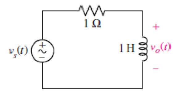
■ FIGURE 10.80
Expert Solution & Answer
Want to see the full answer?
Check out a sample textbook solution
Students have asked these similar questions
An RC circuit consists of a resistor R = 32 Ω, a capacitorC = 25 mF, and an ac generator with an rms voltage of 120 V.(a) At what frequency will the rms current in this circuit be 2.9 A?For this frequency, what are (b) the rms voltage across the resistor,Vrms,R, and (c) the rms voltage across the capacitor, Vrms,C? (d) Showthat Vrms,R + Vrms,C 7 120 V, but that 2V2rms,R + V2rms,C = 120 V.
5. a) Consider the sinusoid x(t) = A cos(2n fot + 0) with fo=100 Hz.
If x(t) is samples at 80 Hz, does aliasing occur. (T/F)
b) Let y(t) = 8 cos(2nt) + 6 cos(22nt) + 8 sin( 32nt) + cos(58nt)
%3D
b-1) Please find Nyquist rate for this signal.
b-2) If we use Fs=5 samples/s, what is the discrete-time signal after
the sampling?
A series RLC circuit is constructed using component values R = 100 £2 and L = 1.5 mH along with a sinusoidal voltage source vs. If Qo= 7, determine (a) the magnitude of the impedance at 500 Mrad/s; (b) the current which flows in response to a voltage vs = 2.5 cos(425 × 10%t) V.
Chapter 10 Solutions
Engineering Circuit Analysis
Ch. 10.1 - Find the angle by which i1 lags v1 if v1 = 120...Ch. 10.2 - Determine values for A, B, C, and if 40 cos(100t ...Ch. 10.2 - Let vs = 40 cos 8000t V in the circuit of Fig....Ch. 10.3 - Prob. 4PCh. 10.3 - If the use of the passive sign convention is...Ch. 10.4 - Let = 2000 rad/s and t = 1 ms. Find the...Ch. 10.4 - Transform each of the following functions of time...Ch. 10.4 - In the circuit of Fig. 10.17, both sources operate...Ch. 10.5 - With reference to the network shown in Fig. 10.19,...Ch. 10.5 - In the frequency-domain circuit of Fig. 10.21,...
Ch. 10.5 - Determine the admittance (in rectangular form) of...Ch. 10.6 - Use nodal analysis on the circuit of Fig. 10.23 to...Ch. 10.6 - Use mesh analysis on the circuit of Fig. 10.25 to...Ch. 10.7 - If superposition is used on the circuit of Fig....Ch. 10.7 - Prob. 15PCh. 10.7 - Determine the current i through the 4 resistor of...Ch. 10.8 - Select some convenient reference value for IC in...Ch. 10 - Evaluate the following: (a) 5 sin (5t 9) at t =...Ch. 10 - (a) Express each of the following as a single...Ch. 10 - Prob. 3ECh. 10 - Prob. 4ECh. 10 - Prob. 5ECh. 10 - Calculate the first three instants in time (t 0)...Ch. 10 - (a) Determine the first two instants in time (t ...Ch. 10 - The concept of Fourier series is a powerful means...Ch. 10 - Household electrical voltages are typically quoted...Ch. 10 - Prob. 10ECh. 10 - Assuming there are no longer any transients...Ch. 10 - Calculate the power dissipated in the 2 resistor...Ch. 10 - Prob. 13ECh. 10 - Prob. 14ECh. 10 - Prob. 15ECh. 10 - Express the following complex numbers in...Ch. 10 - Prob. 17ECh. 10 - Prob. 18ECh. 10 - Evaluate the following, and express your answer in...Ch. 10 - Perform the indicated operations, and express the...Ch. 10 - Insert an appropriate complex source into the...Ch. 10 - For the circuit of Fig. 10.51, if is = 2 cos 5t A,...Ch. 10 - In the circuit depicted in Fig. 10.51, if is is...Ch. 10 - Employ a suitable complex source to determine the...Ch. 10 - Transform each of the following into phasor form:...Ch. 10 - Prob. 26ECh. 10 - Prob. 27ECh. 10 - The following complex voltages are written in a...Ch. 10 - Assuming an operating frequency of 50 Hz, compute...Ch. 10 - Prob. 30ECh. 10 - Prob. 31ECh. 10 - Prob. 32ECh. 10 - Assuming the passive sign convention and an...Ch. 10 - The circuit of Fig. 10.53 is shown represented in...Ch. 10 - (a) Obtain an expression for the equivalent...Ch. 10 - Determine the equivalent impedance of the...Ch. 10 - (a) Obtain an expression for the equivalent...Ch. 10 - Determine the equivalent admittance of the...Ch. 10 - Prob. 40ECh. 10 - Prob. 41ECh. 10 - Find V in Fig. 10.55 if the box contains (a) 3 in...Ch. 10 - Prob. 43ECh. 10 - Prob. 44ECh. 10 - Design a suitable combination of resistors,...Ch. 10 - Design a suitable combination of resistors,...Ch. 10 - For the circuit depicted in Fig. 10.58, (a) redraw...Ch. 10 - For the circuit illustrated in Fig. 10.59, (a)...Ch. 10 - Referring to the circuit of Fig. 10.59, employ...Ch. 10 - In the phasor-domain circuit represented by Fig....Ch. 10 - With regard to the two-mesh phasor-domain circuit...Ch. 10 - Employ phasor analysis techniques to obtain...Ch. 10 - Determine IB in the circuit of Fig. 10.62 if and ....Ch. 10 - Determine V2 in the circuit of Fig. 10.62 if and ....Ch. 10 - Employ phasor analysis to obtain an expression for...Ch. 10 - Determine the current ix in the circuit of Fig....Ch. 10 - Obtain an expression for each of the four...Ch. 10 - Determine the nodal voltages for the circuit of...Ch. 10 - Prob. 59ECh. 10 - Obtain an expression for each of the four mesh...Ch. 10 - Determine the individual contribution each current...Ch. 10 - Determine V1 and V2 in Fig. 10.68 if I1 = 333 mA...Ch. 10 - Prob. 63ECh. 10 - Obtain the Thvenin equivalent seen by the (2 j) ...Ch. 10 - The (2 j) impedance in the circuit of Fig. 10.69...Ch. 10 - With regard to the circuit depicted in Fig. 10.70,...Ch. 10 - Prob. 67ECh. 10 - Determine the individual contribution of each...Ch. 10 - Determine the power dissipated by the 1 resistor...Ch. 10 - The source Is in the circuit of Fig. 10.75 is...Ch. 10 - Prob. 72ECh. 10 - (a) Calculate values for IL, IR, IC, VL, VR, and...Ch. 10 - In the circuit of Fig. 10.77, (a) find values for...Ch. 10 - The voltage source Vs in Fig. 10.78 is chosen such...Ch. 10 - For the circuit shown in Fig. 10.79, (a) draw the...Ch. 10 - For the circuit shown in Fig. 10.80, (a) draw the...Ch. 10 - (a) Replace the inductor in the circuit of Fig....Ch. 10 - Design a purely passive network (containing only...
Knowledge Booster


Learn more about
Need a deep-dive on the concept behind this application? Look no further. Learn more about this topic, electrical-engineering and related others by exploring similar questions and additional content below.Similar questions
- Consider the following causal difference equation, which operates at a sample rate of 8 kHz: 5 3 1 y[n] –žyln – 1] +yln – 2] = x[n]arrow_forwardA resistor of 100 Ω, a coil of 4.50 μH, and a capacitor of 220 pF are in parallel. What is the admittance vector at 6.50 MHz? Provide illustration of the circuit.arrow_forwardProblem 1: A series connected RLC circuit has R = 100 2, L = 200 mH, and C = 5 mF. If the input voltage v(t) = 5 cos(5t) V, find the current i(t) in the circuit. Problem 2: Suppose a resistor with R = 1 k is in parallel with an inductor for which L = w= 1000 rad/s, find the equivalent impedance. 1 mH. Ifarrow_forward
- a) Given the sinusoidal voltage source in a linear o i) The amplitude of the voltage 6 UTM 5 U ii) The angular frequency TM & UTM 5 UTM 8 UTM UTM & UTM iv) The value of V, at 1 = 3 ms 5 UTM 5 UTM 8 [ D UTM 8 UTM 8 UTM UTM UTM & UTarrow_forward8082 A frequency domain represenatation of sinusoids is also know as time domain representaion of sinusoids. True False "Mathematically, in phase means that the phase angle of two waves are the same and its phase difference is zero." True Falsearrow_forwardGiven the following circuit diagram, where the impedances are R = 70, C = -j5 Q & L = j4 2. The voltage source is 3.4*cos(2500nt +90°)B. Find the voltage across the inductor (VL), in polar form, accurate to within 1% and 2º. vS(t) ( VL = C || |1₁ M ww 16 °V Parrow_forward
- Q1: Sketch the single and double sided amplitude and phase spectrum of the following signals: (a) f (t) = -7 sin(3nt) - 5cos (6nt + 90°) (b) f (t) = -4 sin(10°nt) + 8cos (107nt + 170°) (c) f (t) = E=o(-0.5)"cos[n(@,t + 10°)]arrow_forward6. These 3 sinusoids are added together, and sampled every 10 ms. Calculate the first 10 points of the digitized signal, and sketch them. a) u(t)= 10 cos( 12 t +.3) b) v(t)= 5.6 sin(4.4mt-1.2) y(t) = -1.6 cos(-8 t) c)arrow_forwardConsider the system below. For this question, let C (s) = K, in this question K is a positive real number. a) Prove that if the root locus of the system is drawn, the points s1,2=−0.3214 ± 2.8951j will be on the curve. (Show it by doing mathematical calculation without drawing the curve.) b) Draw the root locus of the system. c) It is desired that the dominant (= near the imaginary axis) poles of the closed loop system be at the points s1,2= −0.3214 ± 2.8951j. What should K be for this? What can be said about the stability of the closed loop system for this K value? d) What are the unit step, ramp and parabolic reference tracking errors of the system for K in the option c?arrow_forward
- A series RLC circuit in which R = 1.00 Ω, L = 1.00 mH, and C = 1.00 nF is connected to an AC source delivering 1.00 V (rms). (a) Make a precise graph of the power delivered to the circuit as a function of the frequency and (b) verify that the full width of the resonance peak at halfmaximum is R/2πL.arrow_forwardPlot the phase angle Vs frequency curve on a logarithmic scale.G(S)=10/(S(1+0.1S)(1+0.5S)) Determinearrow_forwardUse the ideal model for the op amp to find the voltage v(t) as a function of time. 9 cos (2000) V 47 k www 60 k 29 nF v(t): 3.19cos(2000t+117.81) V frequency is correct; the phase is wrong of sº Your amplitude is only close (within 5%); thearrow_forward
arrow_back_ios
SEE MORE QUESTIONS
arrow_forward_ios
Recommended textbooks for you
 Introductory Circuit Analysis (13th Edition)Electrical EngineeringISBN:9780133923605Author:Robert L. BoylestadPublisher:PEARSON
 Delmar's Standard Textbook Of ElectricityElectrical EngineeringISBN:9781337900348Author:Stephen L. HermanPublisher:Cengage Learning
 Programmable Logic ControllersElectrical EngineeringISBN:9780073373843Author:Frank D. PetruzellaPublisher:McGraw-Hill Education
 Fundamentals of Electric CircuitsElectrical EngineeringISBN:9780078028229Author:Charles K Alexander, Matthew SadikuPublisher:McGraw-Hill Education
 Electric Circuits. (11th Edition)Electrical EngineeringISBN:9780134746968Author:James W. Nilsson, Susan RiedelPublisher:PEARSON
 Engineering ElectromagneticsElectrical EngineeringISBN:9780078028151Author:Hayt, William H. (william Hart), Jr, BUCK, John A.Publisher:Mcgraw-hill Education,
Introductory Circuit Analysis (13th Edition)
Electrical Engineering
ISBN:9780133923605
Author:Robert L. Boylestad
Publisher:PEARSON
Delmar's Standard Textbook Of Electricity
Electrical Engineering
ISBN:9781337900348
Author:Stephen L. Herman
Publisher:Cengage Learning
Programmable Logic Controllers
Electrical Engineering
ISBN:9780073373843
Author:Frank D. Petruzella
Publisher:McGraw-Hill Education
Fundamentals of Electric Circuits
Electrical Engineering
ISBN:9780078028229
Author:Charles K Alexander, Matthew Sadiku
Publisher:McGraw-Hill Education
Electric Circuits. (11th Edition)
Electrical Engineering
ISBN:9780134746968
Author:James W. Nilsson, Susan Riedel
Publisher:PEARSON
Engineering Electromagnetics
Electrical Engineering
ISBN:9780078028151
Author:Hayt, William H. (william Hart), Jr, BUCK, John A.
Publisher:Mcgraw-hill Education,
Nodal Analysis for Circuits Explained; Author: Engineer4Free;https://www.youtube.com/watch?v=f-sbANgw4fo;License: Standard Youtube License