
Engineering Circuit Analysis
9th Edition
ISBN: 9780073545516
Author: Hayt, William H. (william Hart), Jr, Kemmerly, Jack E. (jack Ellsworth), Durbin, Steven M.
Publisher: Mcgraw-hill Education,
expand_more
expand_more
format_list_bulleted
Videos
Textbook Question
Chapter 10, Problem 55E
Employ phasor analysis to obtain an expression for vx as labeled in the circuit of Fig. 10.63.
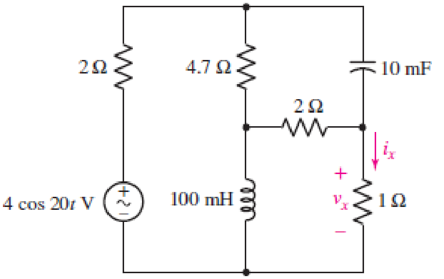
■ FIGURE 10.63
Expert Solution & Answer
Want to see the full answer?
Check out a sample textbook solution
Students have asked these similar questions
If CS=2000H, DS=35A0H, SS=3210H, ES=5890H, BX=42A9H, BP=3400H, find the physical address of the source data for the following instructions. a) MOV AL, [Bx+1500H] b) MOV BL, [BP+05H]
solve this please
Consider the system below. For this question, let C (s) = K, in this question K is a positive real number.
a) Prove that if the root locus of the system is drawn, the points s1,2=−0.3214 ± 2.8951j will be on the curve. (Show it by doing mathematical calculation without drawing the curve.)
b) Draw the root locus of the system.
c) It is desired that the dominant (= near the imaginary axis) poles of the closed loop system be at the points s1,2= −0.3214 ± 2.8951j. What should K be for this? What can be said about the stability of the closed loop system for this K value?
d) What are the unit step, ramp and parabolic reference tracking errors of the system for K in the option c?
S:41)
A circuit consists of a current source, Is = 43 sin(5386t - 40.29 °) mA in parallel with a 72 kΩ resistor and a 2895 pF capacitor. Determine the magnitude of the effective value of current that flows through the resistor.
Chapter 10 Solutions
Engineering Circuit Analysis
Ch. 10.1 - Find the angle by which i1 lags v1 if v1 = 120...Ch. 10.2 - Determine values for A, B, C, and if 40 cos(100t ...Ch. 10.2 - Let vs = 40 cos 8000t V in the circuit of Fig....Ch. 10.3 - Prob. 4PCh. 10.3 - If the use of the passive sign convention is...Ch. 10.4 - Let = 2000 rad/s and t = 1 ms. Find the...Ch. 10.4 - Transform each of the following functions of time...Ch. 10.4 - In the circuit of Fig. 10.17, both sources operate...Ch. 10.5 - With reference to the network shown in Fig. 10.19,...Ch. 10.5 - In the frequency-domain circuit of Fig. 10.21,...
Ch. 10.5 - Determine the admittance (in rectangular form) of...Ch. 10.6 - Use nodal analysis on the circuit of Fig. 10.23 to...Ch. 10.6 - Use mesh analysis on the circuit of Fig. 10.25 to...Ch. 10.7 - If superposition is used on the circuit of Fig....Ch. 10.7 - Prob. 15PCh. 10.7 - Determine the current i through the 4 resistor of...Ch. 10.8 - Select some convenient reference value for IC in...Ch. 10 - Evaluate the following: (a) 5 sin (5t 9) at t =...Ch. 10 - (a) Express each of the following as a single...Ch. 10 - Prob. 3ECh. 10 - Prob. 4ECh. 10 - Prob. 5ECh. 10 - Calculate the first three instants in time (t 0)...Ch. 10 - (a) Determine the first two instants in time (t ...Ch. 10 - The concept of Fourier series is a powerful means...Ch. 10 - Household electrical voltages are typically quoted...Ch. 10 - Prob. 10ECh. 10 - Assuming there are no longer any transients...Ch. 10 - Calculate the power dissipated in the 2 resistor...Ch. 10 - Prob. 13ECh. 10 - Prob. 14ECh. 10 - Prob. 15ECh. 10 - Express the following complex numbers in...Ch. 10 - Prob. 17ECh. 10 - Prob. 18ECh. 10 - Evaluate the following, and express your answer in...Ch. 10 - Perform the indicated operations, and express the...Ch. 10 - Insert an appropriate complex source into the...Ch. 10 - For the circuit of Fig. 10.51, if is = 2 cos 5t A,...Ch. 10 - In the circuit depicted in Fig. 10.51, if is is...Ch. 10 - Employ a suitable complex source to determine the...Ch. 10 - Transform each of the following into phasor form:...Ch. 10 - Prob. 26ECh. 10 - Prob. 27ECh. 10 - The following complex voltages are written in a...Ch. 10 - Assuming an operating frequency of 50 Hz, compute...Ch. 10 - Prob. 30ECh. 10 - Prob. 31ECh. 10 - Prob. 32ECh. 10 - Assuming the passive sign convention and an...Ch. 10 - The circuit of Fig. 10.53 is shown represented in...Ch. 10 - (a) Obtain an expression for the equivalent...Ch. 10 - Determine the equivalent impedance of the...Ch. 10 - (a) Obtain an expression for the equivalent...Ch. 10 - Determine the equivalent admittance of the...Ch. 10 - Prob. 40ECh. 10 - Prob. 41ECh. 10 - Find V in Fig. 10.55 if the box contains (a) 3 in...Ch. 10 - Prob. 43ECh. 10 - Prob. 44ECh. 10 - Design a suitable combination of resistors,...Ch. 10 - Design a suitable combination of resistors,...Ch. 10 - For the circuit depicted in Fig. 10.58, (a) redraw...Ch. 10 - For the circuit illustrated in Fig. 10.59, (a)...Ch. 10 - Referring to the circuit of Fig. 10.59, employ...Ch. 10 - In the phasor-domain circuit represented by Fig....Ch. 10 - With regard to the two-mesh phasor-domain circuit...Ch. 10 - Employ phasor analysis techniques to obtain...Ch. 10 - Determine IB in the circuit of Fig. 10.62 if and ....Ch. 10 - Determine V2 in the circuit of Fig. 10.62 if and ....Ch. 10 - Employ phasor analysis to obtain an expression for...Ch. 10 - Determine the current ix in the circuit of Fig....Ch. 10 - Obtain an expression for each of the four...Ch. 10 - Determine the nodal voltages for the circuit of...Ch. 10 - Prob. 59ECh. 10 - Obtain an expression for each of the four mesh...Ch. 10 - Determine the individual contribution each current...Ch. 10 - Determine V1 and V2 in Fig. 10.68 if I1 = 333 mA...Ch. 10 - Prob. 63ECh. 10 - Obtain the Thvenin equivalent seen by the (2 j) ...Ch. 10 - The (2 j) impedance in the circuit of Fig. 10.69...Ch. 10 - With regard to the circuit depicted in Fig. 10.70,...Ch. 10 - Prob. 67ECh. 10 - Determine the individual contribution of each...Ch. 10 - Determine the power dissipated by the 1 resistor...Ch. 10 - The source Is in the circuit of Fig. 10.75 is...Ch. 10 - Prob. 72ECh. 10 - (a) Calculate values for IL, IR, IC, VL, VR, and...Ch. 10 - In the circuit of Fig. 10.77, (a) find values for...Ch. 10 - The voltage source Vs in Fig. 10.78 is chosen such...Ch. 10 - For the circuit shown in Fig. 10.79, (a) draw the...Ch. 10 - For the circuit shown in Fig. 10.80, (a) draw the...Ch. 10 - (a) Replace the inductor in the circuit of Fig....Ch. 10 - Design a purely passive network (containing only...
Knowledge Booster


Learn more about
Need a deep-dive on the concept behind this application? Look no further. Learn more about this topic, electrical-engineering and related others by exploring similar questions and additional content below.Similar questions
- I. Find the solution of the following differential equation: 1. y'-8y'+4y=2; y(0) = 1, y'(0) = 1 2. y'+ 4y'+ siny=0; y(0) = 1, y'(0)=0arrow_forwardPART B: In series RLC circuit, if R=20 ohm, L=0.6H then for (1) C > 6 mF, the system will result in an * system. (ii) C < 6 mF, the system will result in an system Consider the circuit below. Calculate the value of R needed to have a critically damped response for the circuit given below. R = 60 2 www 0.01 F 4 H ww 10:19 PM ENG 85%arrow_forward98% @ au 18 uaJI 10:48 4 s 4 1440 docs.google.com/forms A bla 10 Q1: As the figure Shawn for t=O, switch 1 is closed and switch 2 is closed 4sec later, find i(t) for * t>O and i for t=2s, and t35s ww S2 ww A OF HS i(i(t)={(0 ts0, 4(1-e^(-2t) ) Osts4, 2.727+1.273e^(-1.466(t-4) t24) )}A ,3.93A, 3.022A i(i(t)={(0 ts0, 4(1-e^(-2t) ) Osts4, 2.727+1.273e^(-1.466(t-4) t24) )}A ,3.93A, 4.022A i(i(t)={(0 ts0, 4(1-e^(-2t) ) Osts4, 2.727+1.273e^(-1.466(t-4) t24) )}A ,2.93A, 3.022A None of them 10:35 AM is parrow_forward
- R = 3 N v-(t) = 325 cos 300t V C = 400 µF V. L = 2 mH Figure Q1 By referring to Figure Q1, answer the following questions. i. Find the respective reactance of the inductor, XL, and capacitor, Xc. (marks) ii. Convert the voltage source from time domain, vs(t), to phasor domain, Vs. (The phasor domain needs to be in r.m.s). ii. Find the total impedance of the circuit. iv. Find vz(t) and iL(t) using Mesh analysis. (Show answer in peak value). Sketch the phasor diagram of VL and IL. V.arrow_forwardFor the circuit shown, determine:a) Plot pole-zero diagram for H = I / Vsb) Based on H, calculate the forced response for i (t) to an excitation:Vs (t) = 5 e-3tsin (50t) cos (60t) [V]arrow_forwardFind the time domain expression corresponding to each phasor: a) V = 18.6 (-54 degree) V b) V = (20 + j80 - 30(15 degree) V Question 1 options:arrow_forward
- A 200 Ω resistor, 0.900 H inductor, and 6.00 µF capacitor are connected in series across a voltage source that has voltage amplitude 30.0 V and an angular frequency of 250 rad/s. (a) What are v, vR, vL, and vC at t = 20.0 ms? Compare vR + vL + vC to v at this instant. (b) What are VR, VL, and VC? Compare V to VR + VL + VC. Explain why these two quantities are not equal.arrow_forwardQ.5) For the following system shown below, determine the characteristic equation, the rise time, settling time, and also calculate the value of K and j so that the peak time is 1 sec, maximum overshoot is 0.2 when a unit step input is applied. K C(s) R(s) s2 + s 1+js Hint: The settling time 4 %3D ts = 4T 8wnarrow_forwardQ. The two sided exponential voltage f(t) = Be-Alt| volt is developed across a 1 2 resistor. 1- Calculate the total energy dissipated in the resistor. When A=22 ,B=98arrow_forward
- 6. In a series circuit containing pure resistance and a pure inductance, the current and the voltage are expressed as: z (f) - 5 sin (314 t + 2 /3) and v (1) 15 sm (3141+5/6) (a) What is the impedance of the circuit? (b) What is the value of the resistance? (c) What is the inductance in henrys ? (d) What is the average power drawn by the circuit? (e) What is the power factor?arrow_forwardQ.5) For the following system shown below, determine the characteristic equation, the rise time, settling time, and also calculate the value of K and j so that the peak time is 1 sec, maximum overshoot is 0.2 when a unit step input is applied. K R(s) C(s) s2 + s 1+js Hint: - The settling time 4 4T ts = %3D Swnarrow_forward3) Plot the root locus far the characteristic equation for a system as K varies for k so, when 544 12 s³+6454+325arrow_forward
arrow_back_ios
SEE MORE QUESTIONS
arrow_forward_ios
Recommended textbooks for you
 Introductory Circuit Analysis (13th Edition)Electrical EngineeringISBN:9780133923605Author:Robert L. BoylestadPublisher:PEARSON
 Delmar's Standard Textbook Of ElectricityElectrical EngineeringISBN:9781337900348Author:Stephen L. HermanPublisher:Cengage Learning
 Programmable Logic ControllersElectrical EngineeringISBN:9780073373843Author:Frank D. PetruzellaPublisher:McGraw-Hill Education
 Fundamentals of Electric CircuitsElectrical EngineeringISBN:9780078028229Author:Charles K Alexander, Matthew SadikuPublisher:McGraw-Hill Education
 Electric Circuits. (11th Edition)Electrical EngineeringISBN:9780134746968Author:James W. Nilsson, Susan RiedelPublisher:PEARSON
 Engineering ElectromagneticsElectrical EngineeringISBN:9780078028151Author:Hayt, William H. (william Hart), Jr, BUCK, John A.Publisher:Mcgraw-hill Education,
Introductory Circuit Analysis (13th Edition)
Electrical Engineering
ISBN:9780133923605
Author:Robert L. Boylestad
Publisher:PEARSON
Delmar's Standard Textbook Of Electricity
Electrical Engineering
ISBN:9781337900348
Author:Stephen L. Herman
Publisher:Cengage Learning
Programmable Logic Controllers
Electrical Engineering
ISBN:9780073373843
Author:Frank D. Petruzella
Publisher:McGraw-Hill Education
Fundamentals of Electric Circuits
Electrical Engineering
ISBN:9780078028229
Author:Charles K Alexander, Matthew Sadiku
Publisher:McGraw-Hill Education
Electric Circuits. (11th Edition)
Electrical Engineering
ISBN:9780134746968
Author:James W. Nilsson, Susan Riedel
Publisher:PEARSON
Engineering Electromagnetics
Electrical Engineering
ISBN:9780078028151
Author:Hayt, William H. (william Hart), Jr, BUCK, John A.
Publisher:Mcgraw-hill Education,
Routh Hurwitz Stability Criterion Basic Worked Example; Author: The Complete Guide to Everything;https://www.youtube.com/watch?v=CzzsR5FT-8U;License: Standard Youtube License