
Engineering Circuit Analysis
9th Edition
ISBN: 9780073545516
Author: Hayt, William H. (william Hart), Jr, Kemmerly, Jack E. (jack Ellsworth), Durbin, Steven M.
Publisher: Mcgraw-hill Education,
expand_more
expand_more
format_list_bulleted
Concept explainers
Videos
Textbook Question
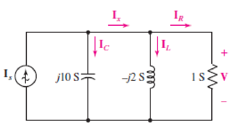
Chapter 10, Problem 71E
The source Is in the circuit of Fig. 10.75 is selected such that
Expert Solution & Answer
Want to see the full answer?
Check out a sample textbook solution
Students have asked these similar questions
680. Given a sinusoidal voltage source in series with R, L, and C. The sin
voltage source has a frequency of 300 Hz.
milliHenry, C=4 microFarad, V=30sin (wt) volts.
phasor current and voltage across the capacitor. I(jw)=Aexp(jB),
vc(jw)=Dexp(jE), Express radian angles between [-pi/2, pi/2]. Find the
corresponding time domain forms.
Ans: D, E, Fs all MKS units.
R=3 Ohms, L=1
Solve for the
i(t)=Fsin(wt+G),
vc(t)=Hsin(wt+K)
ans:4
Calculate the R value in ohms, since the 13kHz frequency sinusoidal sign is observed at the output of the circuit in the picture. (C=10nF)
Consider the circuit shown in the figure below. Find the phasors Is, V, IR, IL, and Ic.-
i,(1) =
0.01 cos(10*)
20 mH
1 k2
0.5 μF
Vir
A
Chapter 10 Solutions
Engineering Circuit Analysis
Ch. 10.1 - Find the angle by which i1 lags v1 if v1 = 120...Ch. 10.2 - Determine values for A, B, C, and if 40 cos(100t ...Ch. 10.2 - Let vs = 40 cos 8000t V in the circuit of Fig....Ch. 10.3 - Prob. 4PCh. 10.3 - If the use of the passive sign convention is...Ch. 10.4 - Let = 2000 rad/s and t = 1 ms. Find the...Ch. 10.4 - Transform each of the following functions of time...Ch. 10.4 - In the circuit of Fig. 10.17, both sources operate...Ch. 10.5 - With reference to the network shown in Fig. 10.19,...Ch. 10.5 - In the frequency-domain circuit of Fig. 10.21,...
Ch. 10.5 - Determine the admittance (in rectangular form) of...Ch. 10.6 - Use nodal analysis on the circuit of Fig. 10.23 to...Ch. 10.6 - Use mesh analysis on the circuit of Fig. 10.25 to...Ch. 10.7 - If superposition is used on the circuit of Fig....Ch. 10.7 - Prob. 15PCh. 10.7 - Determine the current i through the 4 resistor of...Ch. 10.8 - Select some convenient reference value for IC in...Ch. 10 - Evaluate the following: (a) 5 sin (5t 9) at t =...Ch. 10 - (a) Express each of the following as a single...Ch. 10 - Prob. 3ECh. 10 - Prob. 4ECh. 10 - Prob. 5ECh. 10 - Calculate the first three instants in time (t 0)...Ch. 10 - (a) Determine the first two instants in time (t ...Ch. 10 - The concept of Fourier series is a powerful means...Ch. 10 - Household electrical voltages are typically quoted...Ch. 10 - Prob. 10ECh. 10 - Assuming there are no longer any transients...Ch. 10 - Calculate the power dissipated in the 2 resistor...Ch. 10 - Prob. 13ECh. 10 - Prob. 14ECh. 10 - Prob. 15ECh. 10 - Express the following complex numbers in...Ch. 10 - Prob. 17ECh. 10 - Prob. 18ECh. 10 - Evaluate the following, and express your answer in...Ch. 10 - Perform the indicated operations, and express the...Ch. 10 - Insert an appropriate complex source into the...Ch. 10 - For the circuit of Fig. 10.51, if is = 2 cos 5t A,...Ch. 10 - In the circuit depicted in Fig. 10.51, if is is...Ch. 10 - Employ a suitable complex source to determine the...Ch. 10 - Transform each of the following into phasor form:...Ch. 10 - Prob. 26ECh. 10 - Prob. 27ECh. 10 - The following complex voltages are written in a...Ch. 10 - Assuming an operating frequency of 50 Hz, compute...Ch. 10 - Prob. 30ECh. 10 - Prob. 31ECh. 10 - Prob. 32ECh. 10 - Assuming the passive sign convention and an...Ch. 10 - The circuit of Fig. 10.53 is shown represented in...Ch. 10 - (a) Obtain an expression for the equivalent...Ch. 10 - Determine the equivalent impedance of the...Ch. 10 - (a) Obtain an expression for the equivalent...Ch. 10 - Determine the equivalent admittance of the...Ch. 10 - Prob. 40ECh. 10 - Prob. 41ECh. 10 - Find V in Fig. 10.55 if the box contains (a) 3 in...Ch. 10 - Prob. 43ECh. 10 - Prob. 44ECh. 10 - Design a suitable combination of resistors,...Ch. 10 - Design a suitable combination of resistors,...Ch. 10 - For the circuit depicted in Fig. 10.58, (a) redraw...Ch. 10 - For the circuit illustrated in Fig. 10.59, (a)...Ch. 10 - Referring to the circuit of Fig. 10.59, employ...Ch. 10 - In the phasor-domain circuit represented by Fig....Ch. 10 - With regard to the two-mesh phasor-domain circuit...Ch. 10 - Employ phasor analysis techniques to obtain...Ch. 10 - Determine IB in the circuit of Fig. 10.62 if and ....Ch. 10 - Determine V2 in the circuit of Fig. 10.62 if and ....Ch. 10 - Employ phasor analysis to obtain an expression for...Ch. 10 - Determine the current ix in the circuit of Fig....Ch. 10 - Obtain an expression for each of the four...Ch. 10 - Determine the nodal voltages for the circuit of...Ch. 10 - Prob. 59ECh. 10 - Obtain an expression for each of the four mesh...Ch. 10 - Determine the individual contribution each current...Ch. 10 - Determine V1 and V2 in Fig. 10.68 if I1 = 333 mA...Ch. 10 - Prob. 63ECh. 10 - Obtain the Thvenin equivalent seen by the (2 j) ...Ch. 10 - The (2 j) impedance in the circuit of Fig. 10.69...Ch. 10 - With regard to the circuit depicted in Fig. 10.70,...Ch. 10 - Prob. 67ECh. 10 - Determine the individual contribution of each...Ch. 10 - Determine the power dissipated by the 1 resistor...Ch. 10 - The source Is in the circuit of Fig. 10.75 is...Ch. 10 - Prob. 72ECh. 10 - (a) Calculate values for IL, IR, IC, VL, VR, and...Ch. 10 - In the circuit of Fig. 10.77, (a) find values for...Ch. 10 - The voltage source Vs in Fig. 10.78 is chosen such...Ch. 10 - For the circuit shown in Fig. 10.79, (a) draw the...Ch. 10 - For the circuit shown in Fig. 10.80, (a) draw the...Ch. 10 - (a) Replace the inductor in the circuit of Fig....Ch. 10 - Design a purely passive network (containing only...
Knowledge Booster


Learn more about
Need a deep-dive on the concept behind this application? Look no further. Learn more about this topic, electrical-engineering and related others by exploring similar questions and additional content below.Similar questions
- Consider the following causal difference equation, which operates at a sample rate of 8 kHz: 5 3 1 y[n] –žyln – 1] +yln – 2] = x[n]arrow_forward2) Convert these from polar to rectangular form: a) 1045° b) 0.4290° a) b)arrow_forwardConsider the oscilloscope figure shown next (with X(t) signal operating at a frequency of 1 KHz). The Y(t) signal is approximately found to be 3.2sin(4TtKt) None of the choices 2.8sin( 3tKt) 3.2sin(6tKt) 2.8sin(2tkt)arrow_forward
- Given the following voltages: e 1 = -100sin(wt-π/3), e2 = 250cos(wt+ π/6), e3 =150sin(wt+ π/4), e4 = -75coswt, and e5 = -200cos(wt- π/12). Determine theequation of the resultant voltage. Use the component method.arrow_forward4. For the following pairs of sinusoids, determine which one LEADS by how much. (draw the phasor diagram) a, e = 10cos(21 - 21jv and i = Scos(2t - 11)A b. e= 20sin(cat + 50"JV and i = 60cos(at - 10")A e = 311sin(250t + 120")V and i = 15.5sin(2501 - 165)Aarrow_forward1. solve equation of the sinusoidal signal v(t) from the information, where v(t) = Vp sin ωt. Vp-p = 6 div Oscilloscope setting: horizontal = 0.5 ms/div 1 cycle = 8 div vertical amplitude = 0.5 volt/div 2. 1 cycle of 2 sinusoidal signals displayed with 10 kHz on the oscilloscope screen. If the two signals have a difference time with 20µs, what the value of phase shift between two signals/waveforms displayed on the scope screen? 3. It is possible for a circuit made up of a resistor, an inductor, and a capacitor (connected in series or parallel) to behave like a purely resistive circuit. Explain why.arrow_forward
- 1. Fill in the table by converting the values into the equivalent forms. Unless otherwise specified, assume the frequency to be 60HZ. Consider that the table consists of voltage signal values across certain circuit components (i.e. phasor magnitudes are expressed in RMS). Rectangular Form -5+j Phasor Form Time-Domain Function 10 cos (201 + 50°) 1420°arrow_forwardA varactor phase modulator has a resistance value of 2.5 kn. The capacitance of the varactor at the center unmodulated frequency is 30 pF and the carrier frequency is 5 MHz. What is the phase shift? Answer:arrow_forwardIn the circuit of Fig. 10.77, (a) find values for I1, I2, and I3. (b) Show Vs, I1, I2, and I3 on a phasor diagram (scales of 50 V/in and 2 A/in work fine). (c) Find Is graphically and give its amplitude and phase angle.arrow_forward
- Problem 4 For the circuit shown below consider is =5 cos (1000t + 10°) A: a) Find the phasors VS, IR, IC and IL. b) Construct the phasor diagram showing Is, IR, IC and IL and Vs. What is the phase relationship between Is and Vs? is (t) + Vs(t) Tit 4 mH 10 Ω 100 μFarrow_forward10:55 BYV 2.00 Yo 49 (48) KB/S Two coils are A and B ar : Editing 9/7/21 10:55 AM Two coils are A and B are connected in series to a supply of 230V, 50HZ. Coil A has an inductance of 0.2H and a resistance of 20 Q, and coil B has an inductance of 0.05H and a resistance of 60 Q. Calculate the current and its phase angle relative to the supply voltage. Also determine the voltage across each coil. |arrow_forwardGiven the sinusoidal voltage v(t) = 600 cos (400ttt - 60° ) V, find: %3D a) The maximum voltage value b) The effective voltage value c) The angular frequency d) The frequency of the voltage e) The value of the voltage at t = 10 msarrow_forward
arrow_back_ios
SEE MORE QUESTIONS
arrow_forward_ios
Recommended textbooks for you
 Introductory Circuit Analysis (13th Edition)Electrical EngineeringISBN:9780133923605Author:Robert L. BoylestadPublisher:PEARSON
 Delmar's Standard Textbook Of ElectricityElectrical EngineeringISBN:9781337900348Author:Stephen L. HermanPublisher:Cengage Learning
 Programmable Logic ControllersElectrical EngineeringISBN:9780073373843Author:Frank D. PetruzellaPublisher:McGraw-Hill Education
 Fundamentals of Electric CircuitsElectrical EngineeringISBN:9780078028229Author:Charles K Alexander, Matthew SadikuPublisher:McGraw-Hill Education
 Electric Circuits. (11th Edition)Electrical EngineeringISBN:9780134746968Author:James W. Nilsson, Susan RiedelPublisher:PEARSON
 Engineering ElectromagneticsElectrical EngineeringISBN:9780078028151Author:Hayt, William H. (william Hart), Jr, BUCK, John A.Publisher:Mcgraw-hill Education,
Introductory Circuit Analysis (13th Edition)
Electrical Engineering
ISBN:9780133923605
Author:Robert L. Boylestad
Publisher:PEARSON
Delmar's Standard Textbook Of Electricity
Electrical Engineering
ISBN:9781337900348
Author:Stephen L. Herman
Publisher:Cengage Learning
Programmable Logic Controllers
Electrical Engineering
ISBN:9780073373843
Author:Frank D. Petruzella
Publisher:McGraw-Hill Education
Fundamentals of Electric Circuits
Electrical Engineering
ISBN:9780078028229
Author:Charles K Alexander, Matthew Sadiku
Publisher:McGraw-Hill Education
Electric Circuits. (11th Edition)
Electrical Engineering
ISBN:9780134746968
Author:James W. Nilsson, Susan Riedel
Publisher:PEARSON
Engineering Electromagnetics
Electrical Engineering
ISBN:9780078028151
Author:Hayt, William H. (william Hart), Jr, BUCK, John A.
Publisher:Mcgraw-hill Education,
Nodal Analysis for Circuits Explained; Author: Engineer4Free;https://www.youtube.com/watch?v=f-sbANgw4fo;License: Standard Youtube License