
Engineering Circuit Analysis
9th Edition
ISBN: 9780073545516
Author: Hayt, William H. (william Hart), Jr, Kemmerly, Jack E. (jack Ellsworth), Durbin, Steven M.
Publisher: Mcgraw-hill Education,
expand_more
expand_more
format_list_bulleted
Concept explainers
Videos
Textbook Question
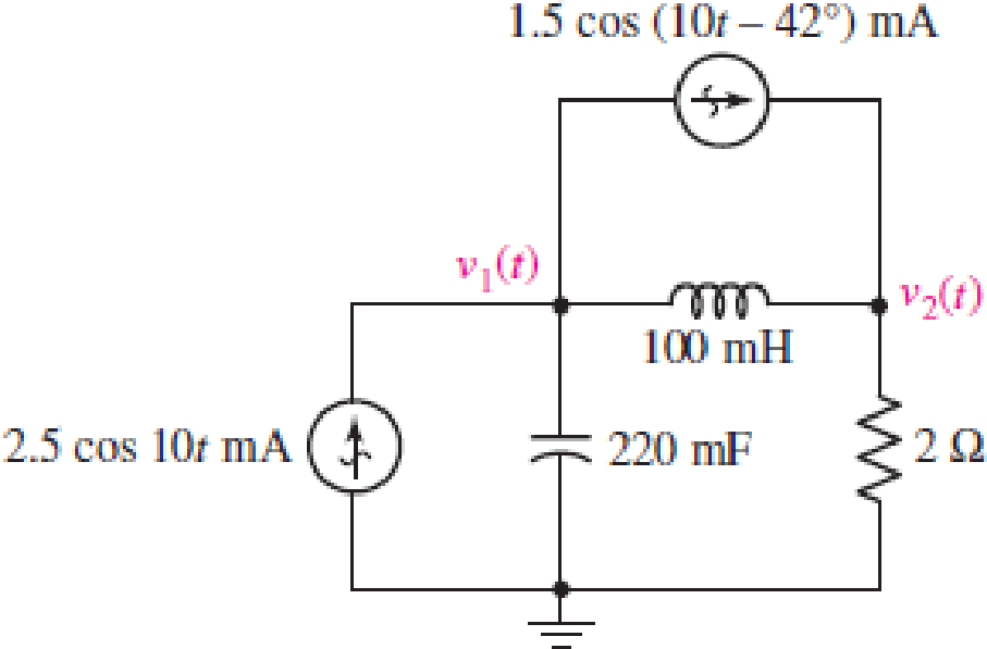
Chapter 10, Problem 48E
For the circuit illustrated in Fig. 10.59, (a) redraw, labeling appropriate phasor and impedance quantities; (b) determine expressions for the three time-domain mesh currents.
FIGURE 10.59
Expert Solution & Answer
Want to see the full answer?
Check out a sample textbook solution
Students have asked these similar questions
In a linear circuit, the voltage source is
v, = 12 sin(10t +24°) V
(a) What is the angular frequency of the voltage?
(b) What is the frequency of the source?
(c) Find the period of the voltage.
(d) Express vs in cosine form.
(e) Determine vs at t 2.5 ms.
1. Fill in the table by converting the values into the equivalent forms. Unless otherwise specified, assume the frequency to be
60HZ. Consider that the table consists of voltage signal values across certain circuit components (i.e. phasor magnitudes
are expressed in RMS).
Rectangular Form
-5+j
Phasor Form
Time-Domain Function
10 cos (201 + 50°)
1420°
True
False
If a type 1 system is
subjected to parabolic input,
the value of steady state
error will be zero.
In block diagram
representation, the lines
connecting the blocks,
known as branches.
The output signal is fed back
at the input side from the
Summing point.
Chapter 10 Solutions
Engineering Circuit Analysis
Ch. 10.1 - Find the angle by which i1 lags v1 if v1 = 120...Ch. 10.2 - Determine values for A, B, C, and if 40 cos(100t ...Ch. 10.2 - Let vs = 40 cos 8000t V in the circuit of Fig....Ch. 10.3 - Prob. 4PCh. 10.3 - If the use of the passive sign convention is...Ch. 10.4 - Let = 2000 rad/s and t = 1 ms. Find the...Ch. 10.4 - Transform each of the following functions of time...Ch. 10.4 - In the circuit of Fig. 10.17, both sources operate...Ch. 10.5 - With reference to the network shown in Fig. 10.19,...Ch. 10.5 - In the frequency-domain circuit of Fig. 10.21,...
Ch. 10.5 - Determine the admittance (in rectangular form) of...Ch. 10.6 - Use nodal analysis on the circuit of Fig. 10.23 to...Ch. 10.6 - Use mesh analysis on the circuit of Fig. 10.25 to...Ch. 10.7 - If superposition is used on the circuit of Fig....Ch. 10.7 - Prob. 15PCh. 10.7 - Determine the current i through the 4 resistor of...Ch. 10.8 - Select some convenient reference value for IC in...Ch. 10 - Evaluate the following: (a) 5 sin (5t 9) at t =...Ch. 10 - (a) Express each of the following as a single...Ch. 10 - Prob. 3ECh. 10 - Prob. 4ECh. 10 - Prob. 5ECh. 10 - Calculate the first three instants in time (t 0)...Ch. 10 - (a) Determine the first two instants in time (t ...Ch. 10 - The concept of Fourier series is a powerful means...Ch. 10 - Household electrical voltages are typically quoted...Ch. 10 - Prob. 10ECh. 10 - Assuming there are no longer any transients...Ch. 10 - Calculate the power dissipated in the 2 resistor...Ch. 10 - Prob. 13ECh. 10 - Prob. 14ECh. 10 - Prob. 15ECh. 10 - Express the following complex numbers in...Ch. 10 - Prob. 17ECh. 10 - Prob. 18ECh. 10 - Evaluate the following, and express your answer in...Ch. 10 - Perform the indicated operations, and express the...Ch. 10 - Insert an appropriate complex source into the...Ch. 10 - For the circuit of Fig. 10.51, if is = 2 cos 5t A,...Ch. 10 - In the circuit depicted in Fig. 10.51, if is is...Ch. 10 - Employ a suitable complex source to determine the...Ch. 10 - Transform each of the following into phasor form:...Ch. 10 - Prob. 26ECh. 10 - Prob. 27ECh. 10 - The following complex voltages are written in a...Ch. 10 - Assuming an operating frequency of 50 Hz, compute...Ch. 10 - Prob. 30ECh. 10 - Prob. 31ECh. 10 - Prob. 32ECh. 10 - Assuming the passive sign convention and an...Ch. 10 - The circuit of Fig. 10.53 is shown represented in...Ch. 10 - (a) Obtain an expression for the equivalent...Ch. 10 - Determine the equivalent impedance of the...Ch. 10 - (a) Obtain an expression for the equivalent...Ch. 10 - Determine the equivalent admittance of the...Ch. 10 - Prob. 40ECh. 10 - Prob. 41ECh. 10 - Find V in Fig. 10.55 if the box contains (a) 3 in...Ch. 10 - Prob. 43ECh. 10 - Prob. 44ECh. 10 - Design a suitable combination of resistors,...Ch. 10 - Design a suitable combination of resistors,...Ch. 10 - For the circuit depicted in Fig. 10.58, (a) redraw...Ch. 10 - For the circuit illustrated in Fig. 10.59, (a)...Ch. 10 - Referring to the circuit of Fig. 10.59, employ...Ch. 10 - In the phasor-domain circuit represented by Fig....Ch. 10 - With regard to the two-mesh phasor-domain circuit...Ch. 10 - Employ phasor analysis techniques to obtain...Ch. 10 - Determine IB in the circuit of Fig. 10.62 if and ....Ch. 10 - Determine V2 in the circuit of Fig. 10.62 if and ....Ch. 10 - Employ phasor analysis to obtain an expression for...Ch. 10 - Determine the current ix in the circuit of Fig....Ch. 10 - Obtain an expression for each of the four...Ch. 10 - Determine the nodal voltages for the circuit of...Ch. 10 - Prob. 59ECh. 10 - Obtain an expression for each of the four mesh...Ch. 10 - Determine the individual contribution each current...Ch. 10 - Determine V1 and V2 in Fig. 10.68 if I1 = 333 mA...Ch. 10 - Prob. 63ECh. 10 - Obtain the Thvenin equivalent seen by the (2 j) ...Ch. 10 - The (2 j) impedance in the circuit of Fig. 10.69...Ch. 10 - With regard to the circuit depicted in Fig. 10.70,...Ch. 10 - Prob. 67ECh. 10 - Determine the individual contribution of each...Ch. 10 - Determine the power dissipated by the 1 resistor...Ch. 10 - The source Is in the circuit of Fig. 10.75 is...Ch. 10 - Prob. 72ECh. 10 - (a) Calculate values for IL, IR, IC, VL, VR, and...Ch. 10 - In the circuit of Fig. 10.77, (a) find values for...Ch. 10 - The voltage source Vs in Fig. 10.78 is chosen such...Ch. 10 - For the circuit shown in Fig. 10.79, (a) draw the...Ch. 10 - For the circuit shown in Fig. 10.80, (a) draw the...Ch. 10 - (a) Replace the inductor in the circuit of Fig....Ch. 10 - Design a purely passive network (containing only...
Knowledge Booster


Learn more about
Need a deep-dive on the concept behind this application? Look no further. Learn more about this topic, electrical-engineering and related others by exploring similar questions and additional content below.Similar questions
- 2. What is the value of a sinusoidal voltage at 5 us (micro second) from the positive going zero crossing when V, = 20V and f = 50KHZ ? %3D 3. A sinusoidal voltage is applied to the circuit below. Determine the following: Ip, Ims, lavg, Ipp-arrow_forwardConsider an ac circuit containing a capacitor (Xc = 300 ) and having a source voltage Es of 100 V. Calculate the reactive power Qc in the capacitor.arrow_forwardExplain the phase difference between pure resistor, pure inductor and pure capacitor circuit in detail in an AC circuit. Note : ( please write details by words)arrow_forward
- 4. a. Design a combination of at least one resistor, one inductor, and one capacitor in series to create an equivalent impedance of 300-j400 Q at a frequency of 10,000 rad/s. (Note that there are many potential solutions to this problem.) b. At what frequency does the circuit from part a) have an impedance that is purely resistive?arrow_forward1 A resistance of 20ohms, an inductor of 0.2H and a capacitance of 100uF are connected in series across 220V 50HZ.Determine a)impedance, b)current, c) voltage across R,L and C, d) power in watts and VA, e)p.f. and angle of lag, f) draw the circuit and diagram.arrow_forwardFind the equivalent impedance Zeq seen by the source when Vs = 4 cos (2t) v, C = 1 F, R = 3 2 and L = 0.5 H. (Give angles in degrees and round final answers to two decimal places.) Calculate the voltage across each component - capacitor, resistor and inductor. (Give angles in degrees and round final answers to two decimal places.) Vs R The equivalent impedance seen by the source is Q. The voltage across the capacitor is The voltage across the resistor is The voltage across the inductor is at an angle of at an angle of at an angle of + V. V. V. Q= at an angle ofarrow_forward
- A circuit has a resistance of 12 Q and capacitive reactance of 16 Q in series. If the applied voltage is v= 262 sin (314 t) volts. Determine i) The expression for the current as function of time. ii) The R.M.S values of voltage and current. iii) The active and reactive power of the circuit. iv) Draw the phasor diagram taking current as reference phasor.arrow_forwardA resistor, an inductor, and a capacitor are connected in parallel to an ac source with voltage amplitude V and angular frequency v. Let the source voltage be given by v = Vcosvt. (a) Show that each of the instantaneous voltages vR, vL, and vC at any instant is equal to v and that i = iR + iL + iC, where i is the current through the source and iR, iL, and iC are the currents through the resistor, inductor, and capacitor, respectively. (b) What are the phases of iR, iL, and iC with respect to v? Use current phasors to represent i, iR, iL, and iC. In a phasor diagram, show the phases of these four currents with respect to v. (c) Use the phasor diagram of part (b) to show that the current amplitude I for the current i through the source is I = √(I2R) + (IC - IL)2 . (d) Show that the result of part (c) can be written as I = V/Z, with 1/Z = √ (1/R2) + [ωC - (1/ωL)]2.arrow_forward5. A voltage v(t) = 230 sin ot when applied to a circuit supplies a current given by the expression i(t) = 8cosot +8cos(@t + 60°) +6sin(t +30°)+2sin(@t – 30°)A (a) Using phasor diagram or otherwise, find the amplitude or maximum value of the 14. A oh current. [Ans. 114] (Ans 90 07 15. Th (b) Find the phase angle between the voltage and the currentarrow_forward
- A circuit has a resistance of 12 Q and capacitive reactance of 16 2 in series. If the applied voltage is v= 262 sin (314 t) volts. Determine i) The expression for the current as function of time. ii) The R.M.S values of voltage and current. ii) The active and reactive power of the circuit. iv) Draw the phasor diagram taking current as reference phasor.arrow_forwardConsider the circuit shown in figure Q1. let vs (t) =120 Cos (314t -50°) V. (a) Construct the frequency domain equivalent circuit. (b) Find the steady-state expressions for iot). 7Ω 120 mH ww 120 µF Vs ioo Figure Q1 [1 Marks]arrow_forwardCalculate the mathematical expression of the signal on the oscilloscope screen given in the figure. The position of the GND line is marked on the screenshot. Volts / Div = 4 V and Time / Div = 6.5ms. wwww www www w barrow_forward
arrow_back_ios
SEE MORE QUESTIONS
arrow_forward_ios
Recommended textbooks for you
 Introductory Circuit Analysis (13th Edition)Electrical EngineeringISBN:9780133923605Author:Robert L. BoylestadPublisher:PEARSON
 Delmar's Standard Textbook Of ElectricityElectrical EngineeringISBN:9781337900348Author:Stephen L. HermanPublisher:Cengage Learning
 Programmable Logic ControllersElectrical EngineeringISBN:9780073373843Author:Frank D. PetruzellaPublisher:McGraw-Hill Education
 Fundamentals of Electric CircuitsElectrical EngineeringISBN:9780078028229Author:Charles K Alexander, Matthew SadikuPublisher:McGraw-Hill Education
 Electric Circuits. (11th Edition)Electrical EngineeringISBN:9780134746968Author:James W. Nilsson, Susan RiedelPublisher:PEARSON
 Engineering ElectromagneticsElectrical EngineeringISBN:9780078028151Author:Hayt, William H. (william Hart), Jr, BUCK, John A.Publisher:Mcgraw-hill Education,
Introductory Circuit Analysis (13th Edition)
Electrical Engineering
ISBN:9780133923605
Author:Robert L. Boylestad
Publisher:PEARSON
Delmar's Standard Textbook Of Electricity
Electrical Engineering
ISBN:9781337900348
Author:Stephen L. Herman
Publisher:Cengage Learning
Programmable Logic Controllers
Electrical Engineering
ISBN:9780073373843
Author:Frank D. Petruzella
Publisher:McGraw-Hill Education
Fundamentals of Electric Circuits
Electrical Engineering
ISBN:9780078028229
Author:Charles K Alexander, Matthew Sadiku
Publisher:McGraw-Hill Education
Electric Circuits. (11th Edition)
Electrical Engineering
ISBN:9780134746968
Author:James W. Nilsson, Susan Riedel
Publisher:PEARSON
Engineering Electromagnetics
Electrical Engineering
ISBN:9780078028151
Author:Hayt, William H. (william Hart), Jr, BUCK, John A.
Publisher:Mcgraw-hill Education,
Nodal Analysis for Circuits Explained; Author: Engineer4Free;https://www.youtube.com/watch?v=f-sbANgw4fo;License: Standard Youtube License