
Principles of Geotechnical Engineering (MindTap Course List)
9th Edition
ISBN: 9781305970939
Author: Braja M. Das, Khaled Sobhan
Publisher: Cengage Learning
expand_more
expand_more
format_list_bulleted
Concept explainers
Videos
Textbook Question
Chapter 10, Problem 10.21P
Refer to Figure 10.48. If R = 4 m and hw = height of water = 5 m, determine the vertical stress increases 2 m below the loaded area at radial distances where r = 0, 2, 4, 6, and 8 m.
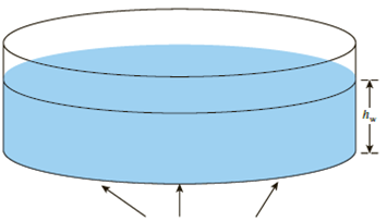
Circular contact area of radius R on the ground surface
Figure 10.48
Expert Solution & Answer
Want to see the full answer?
Check out a sample textbook solution
Students have asked these similar questions
3- Due to application of line loads q1 and q2, the vertical stress increase at point A is 42 lb/ft?. Determine the
magnitude of q2
q.=292 Ib/ft
92
45°
4.5 ft
3 ft
3 ft
A
1. Three point loads, 19000, 20000 and 18000kN, act in line 8 m, 6m apart near the surface
of a soil mass. Calculate the vertical stress at a depth of 4m vertically below the center (30000kN)
load.
19 000 KN
20 000 kN
18 000 KN
Influence factors for vertical stress due to point load
↳
riz
b
riz
1₂
0.478
0.80
0.139
0.020
0.466
0.90
0.108
0.016
0.433
1.00
0.084
0.013
4 m
0.385
1.10
0.066
0.011
0.329
1.20
0.051
0.009
0.273
1.30
0.040
0.006
0.221
1.40
0.032
0.004
0.176
1.50
0.025
0.003
8 m
6m
riz
0.00
0.10
0.20
0.30
0.40
0.50
0.60
0.70
1.60
1.70
1.80
1.90
2.00
2.20
2.40
2.60
A strip load of q = 900 lb/ft2 is applied over
%3D
a width, B = 36 ft. Given: x = 21 ft the
%3D
increase in vertical stress at point A located
z= 15 ft below the surface is (Ib/ft2)
B
q = load per unit area
Δα
162 O
152
142 O
Chapter 10 Solutions
Principles of Geotechnical Engineering (MindTap Course List)
Ch. 10 - Prob. 10.1PCh. 10 - Prob. 10.2PCh. 10 - Prob. 10.3PCh. 10 - Prob. 10.4PCh. 10 - Prob. 10.5PCh. 10 - Prob. 10.6PCh. 10 - Point loads of magnitude 125, 250, and 500 kN act...Ch. 10 - Refer to Figure 10.41. Determine the vertical...Ch. 10 - For the same line loads given in Problem 10.8,...Ch. 10 - Refer to Figure 10.41. Given: q2 = 3800 lb/ft, x1...
Ch. 10 - Refer to Figure 10.42. Due to application of line...Ch. 10 - Refer to Figure 10.43. A strip load of q = 1450...Ch. 10 - Repeat Problem 10.12 for q = 700 kN/m2, B = 8 m,...Ch. 10 - Prob. 10.14PCh. 10 - For the embankment shown in Figure 10.45,...Ch. 10 - Refer to Figure 10.46. A flexible circular area of...Ch. 10 - Refer to Figure 10.47. A flexible rectangular area...Ch. 10 - Refer to the flexible loaded rectangular area...Ch. 10 - Prob. 10.19PCh. 10 - Prob. 10.20PCh. 10 - Refer to Figure 10.48. If R = 4 m and hw = height...Ch. 10 - Refer to Figure 10.49. For the linearly increasing...Ch. 10 - EB and FG are two planes inside a soil element...Ch. 10 - A soil element beneath a pave ment experiences...
Knowledge Booster


Learn more about
Need a deep-dive on the concept behind this application? Look no further. Learn more about this topic, civil-engineering and related others by exploring similar questions and additional content below.Similar questions
- Problem 2 Two 10-kN forces are applied to a 20 x 60-mm rectangular bar as shown. Determine the stress at point A when (a) b = 0, (b) b = 10 mm, (c) b = 25 mm. 10 mm 10 mm 30 mm 10 kN 30 mm 10 kN 25 mmarrow_forward%3D Determine the average normal stress in each bar if the diameter of each bar is 20 mm. Set P = 40 kN. TAC (TBC AB 1.5 m 2 marrow_forwardEx3: 50, 100, and 150 kN point loads are applied at Points A, B, and C, respectively, on the ground surface as seen in the figure. Compute the vertical stress increment under Point D down to the depth z = 20 m. 7.5 m 150 kN 50 kN 2m 5 m (Plane view) 100 kN 3 marrow_forward
- A rectangular concrete slab, 4.a m. x 5.d m. is shown in Figure 3.5, rests on the surface of a soil mass. The load acting on the center of the slah is 1785KN. Determine: 'The soil stress just below the slab. ;) The vertical stress increase at point A. a. b. Plan A 4.5 m Cross Section 3.8 m A 3.1 m Figure 3.5 5.3 marrow_forwardRepeat Problem 10.12 for q = 700 kN/m2, B = 8 m, and z = 4 m. In this case, point A is located below the centerline under the strip load. 10.12 Refer to Figure 10.43. A strip load of q = 1450 lb/ft2 is applied over a width with B = 48 ft. Determine the increase in vertical stress at point A located z = 21 ft below the surface. Given x = 28.8 ft. Figure 10.43arrow_forwardRefer to Figure 10.43. A strip load of q = 1450 lb/ft2 is applied over a width with B = 48 ft. Determine the increase in vertical stress at point A located z = 21 ft below the surface. Given x = 28.8 ft. Figure 10.43arrow_forward
- Question 03: Determine the normal stress and draw the stress diagram of the beam at a point 1 m from the left support. 1.0m 20KN/M D ↓ ↓ ↓ ↓ J J 2.0m 1=225x106mm² Bean depth = z 300mmarrow_forwardINDUCED LOADS ARE APPLIED ON THE GROUND SURFACE AS SHOWN. POINT LOADS: PA= 250KN PB= 175KN PC= 300KN LINE LOAD: Q1= 150KN/M Q2= 225KN/M DETERMINE: a. THE TOTAL VERTICAL STRESS INCREASE AT POINT A AT A DEPTH OF 5M DIRECTLY UNDERNEATH LINE AB.b. THE TOTAL VERTICAL STRESS INCREASE AT POINT O, 8M FROM A TO THE POSITIVE Y AXIS, PERPENDICULAR TO LINE AB AT THE SAME DEPTH.c. THE TOTAL VERTICAL STRESS INCREASE DIRECTLY AT A POINT BELOW THE LINE LOAD 1, PERPENDICULAR TO POINT O AT THE SAME DEPTH.arrow_forward2. The Bar shown is subjected to a tensile load of 150 kN. If the stress in the middle portion is limited to 160 N/mm², determine the diameter of the middle portion. Find also the length of the middle portion if the total elongation of the bar is to be .25cm. Young's modulus is given as equal to 2.0 x 10⁵ N/mm². 150 KN 10 cm DIA 45 cm 10 cm DIA 150 KNarrow_forward
- A rectangular concrete slab, 3m x 4.5m shown in Figure 05.12, rests on the surface of a soil mass. The load on the slab is 1620 kN.1.) Determine the soil stress below the slab2.) Determine the vertical stress increase at point A3.) Determine the vertical stress increase at point B.arrow_forwardb = 3 ft., L=5 ft., T=500 ft-lb CCW, P = 500 lb Dia. = 10 in., Area = 78.54 in^2, Ix=ly=D491 in^4, J = 982 in^4 1. Find APPLIED V, N, Mx, My, Mz at section where A is located looking in from y- axis 2. Calculate the normal stress at point A 3. Calculate the shear stress at point Aarrow_forwardA soil profile consists of a clay layer underlain by a sand layers as shown. A tube is inserted into the bottom sand layer and the water level rises to 1.2m above the ground surface. Determine the effective stress at pt. A Determine the effective stress at pt. B. Determine the effective stress at pt. C Please answer this asap. For upvote. Thank you very mucharrow_forward
arrow_back_ios
SEE MORE QUESTIONS
arrow_forward_ios
Recommended textbooks for you
 Principles of Geotechnical Engineering (MindTap C...Civil EngineeringISBN:9781305970939Author:Braja M. Das, Khaled SobhanPublisher:Cengage Learning
Principles of Geotechnical Engineering (MindTap C...
Civil Engineering
ISBN:9781305970939
Author:Braja M. Das, Khaled Sobhan
Publisher:Cengage Learning
Stress Distribution in Soils GATE 2019 Civil | Boussinesq, Westergaard Theory; Author: Gradeup- GATE, ESE, PSUs Exam Preparation;https://www.youtube.com/watch?v=6e7yIx2VxI0;License: Standard YouTube License, CC-BY