
Elements Of Electromagnetics
7th Edition
ISBN: 9780190698614
Author: Sadiku, Matthew N. O.
Publisher: Oxford University Press
expand_more
expand_more
format_list_bulleted
Related questions
Question
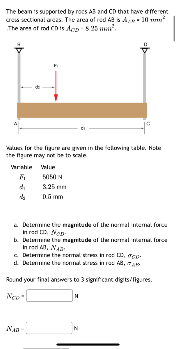

Transcribed Image Text:The beam is supported by rods AB and CD that have different
cross-sectional areas. The area of rod AB is AAB = 10 mm²
.The area of rod CD is Acp = 8.25 mm².
B
F₁
Values for the figure are given in the following table. Note
the figure may not be to scale.
Variable Value
F₁
d₁
d₂
NAB=
5050 N
3.25 mm
0.5 mm
a. Determine the magnitude of the normal internal force
in rod CD, NCD.
b. Determine the magnitude of the normal internal force
in rod AB, NAB.
c. Determine the normal stress in rod CD, OCD.
d. Determine the normal stress in rod AB, O AB.
Round your final answers to 3 significant digits/figures.
NCD =
N
N

Transcribed Image Text:Variable
F₁
d₁
d₂
Values for the figure are given in the following table. Note
the figure may not be to scale.
NAB =
d2
OCD=
F₁
AB=
Value
a.
Determine the magnitude of the normal internal force
in rod CD, NCD.
b. Determine the magnitude of the normal internal force
in rod AB, NAB.
c. Determine the normal stress in rod CD, OCD.
d. Determine the normal stress in rod AB, O AB.
Round your final answers to 3 significant digits/figures.
NCD=
5050 N
3.25 mm
0.5 mm
d₁
N
N
MPa
MPa
Expert Solution
This question has been solved!
Explore an expertly crafted, step-by-step solution for a thorough understanding of key concepts.

Step by stepSolved in 4 steps with 4 images

Knowledge Booster


Learn more about
Need a deep-dive on the concept behind this application? Look no further. Learn more about this topic, mechanical-engineering and related others by exploring similar questions and additional content below.Similar questions
- Calcuate Shear and Bending From Point A to Point B and Point A to Point C. Draw a FBD from point A to point B and another for point A to C indicating what stresses are been calculate. Use the stress tensor and stress cube to Indicate what forces are acting at point A. Force apply at point B is 70lb Distacen from Point A to B is 12 in or 1 feet long Distacen from Point A to C is 3 in Handle diameter 0.625 inarrow_forwardQuestion 5 Determine the magnitude of maximum stress F+ W w = 90 mm h = 15 mm r = 6 mm t = 10 mm F = 9000 N th d LL F w = bar width h = notch height r = notch radius t = bar thickness F = applied force What is the magnitude of the maximum stress at the tip of the notches?arrow_forwardAs a way to check my workarrow_forward
- Please work out part A and Barrow_forwardQ: The soil element with known stress conditions is shown in following figure. (i) construct Mohr's circle for the soil element and determine (ii) stress condition of the plane AC (use double angel method); (iii) major and minor principal stresses; (iv) the angle between major principal plane and the plane "AD" ; (v) maximum shear stress. Provide your answer up to one decimal point. [use graph paper to draw Mohr's circle] 2 kN/m² 6 kN/m² + + B D 2 kN/m² 2 kN/m²arrow_forwardA steel bolt has a diameter of 8 mm. The bolt is encased by a bronze tube that has an outer diameter of 15 mm and inner diameter of 8 mm. A force is applied to the bolt. F d3 d1 F Values for the figure are given in the following table. Note the figure may not be to scale. Variable F₁ Value 25 kN Esteel 200 GPa Ebronze 105 GPa a. Determine the magnitude of the normal force in the steel bolt, Nsteel. b. Determine the magnitude of the normal force in the bronze tube, Nbronze. c. Determine the magnitude of the normal stress in the steel bolt, σ steel. d. Determine the magnitude of the normal stress in the bronze tube, Obronze. Round your final answers to 3 significant digits. N steel = KN Nbronze = KN σ steel = MPa Obronze = MPaarrow_forward
- Consider the frame in (Figure 1). The crate weighs 400 lb. Follow the sign convention. Figure 4 ft A B 1.5 ft 1.5 ft 1.5 ft 1.5 ft F /C . E 0 D 0.4 ft < 1 of 1 ▼ Part D Determine the normal force at point E. Express your answer in pounds to three significant figures. NE = Submit Part E VE = Submit Determine the shear force at point E. Express your answer in pounds to three significant figures. Part F [5] 195| ΑΣΦ | 11 | vec 4 Request Answer ME = Π| ΑΣΦ I Request Answer vec Determine the moment at point E. Express your answer in pound-feet to three significant figures. [V=| ΑΣΦ www. vec ? ? ? lb lb lb-ftarrow_forwardCalcuate Bending From Point A to Point B and Point A to Point C also Torsion from Point A to Point C. Draw a FBD from point A to point B and another for point A to C indicating what stresses are been calculate. Use the stress tensor and stress cube to Indicate what forces are acting at point A. Force apply at point B is 70lb Distacen from Point A to B is 12 in or 1 feet long Distacen from Point A to C is 3 in Handle diameter 0.625 inarrow_forwardCalcuate Shear and Bending From Point A to Point B and Point A to Point C. Draw a FBD from point A to point B and another for point A to C indicating what stresses are been calculate. Use the stress tensor and stress cube to Indicate what forces are acting at point A. Force apply at point B is 70lb Distacen from Point A to B is 12 in or 1 feet long Distacen from Point A to C is 3 in Handle diameter 0.625 inarrow_forward
- why the expert here wrote -200 cos 75 when Σ Fx = 0 , I understand all steps but how he got - 200 cos 75 ( for the force ) (how the angle is 75 ) can you please clarify for me this point please ...... because I did not got the angle 75 dgree for 200 N force can you draw a diagrm for me please to see how 75 dgree links to 200 Narrow_forwardFor the given state of stress, determine the normal and shearing stresses exerted on the oblique face of the shaded triangular element shown. Use a method of analysis based on the equilibrium of that element. Take X = 150 MPa. 60 MPa 45 MPa 70° [m] X The normal stress exerted on the oblique face of the shaded triangular element is The shear stress exerted on the oblique face of the shaded triangular element is MPa. MPa.arrow_forwardSolve show all stepsarrow_forward
arrow_back_ios
SEE MORE QUESTIONS
arrow_forward_ios
Recommended textbooks for you
- Elements Of ElectromagneticsMechanical EngineeringISBN:9780190698614Author:Sadiku, Matthew N. O.Publisher:Oxford University Press
 Mechanics of Materials (10th Edition)Mechanical EngineeringISBN:9780134319650Author:Russell C. HibbelerPublisher:PEARSON
 Thermodynamics: An Engineering ApproachMechanical EngineeringISBN:9781259822674Author:Yunus A. Cengel Dr., Michael A. BolesPublisher:McGraw-Hill Education
  Control Systems EngineeringMechanical EngineeringISBN:9781118170519Author:Norman S. NisePublisher:WILEY
 Mechanics of Materials (MindTap Course List)Mechanical EngineeringISBN:9781337093347Author:Barry J. Goodno, James M. GerePublisher:Cengage Learning
 Engineering Mechanics: StaticsMechanical EngineeringISBN:9781118807330Author:James L. Meriam, L. G. Kraige, J. N. BoltonPublisher:WILEY
Elements Of Electromagnetics
Mechanical Engineering
ISBN:9780190698614
Author:Sadiku, Matthew N. O.
Publisher:Oxford University Press
Mechanics of Materials (10th Edition)
Mechanical Engineering
ISBN:9780134319650
Author:Russell C. Hibbeler
Publisher:PEARSON
Thermodynamics: An Engineering Approach
Mechanical Engineering
ISBN:9781259822674
Author:Yunus A. Cengel Dr., Michael A. Boles
Publisher:McGraw-Hill Education
Control Systems Engineering
Mechanical Engineering
ISBN:9781118170519
Author:Norman S. Nise
Publisher:WILEY
Mechanics of Materials (MindTap Course List)
Mechanical Engineering
ISBN:9781337093347
Author:Barry J. Goodno, James M. Gere
Publisher:Cengage Learning
Engineering Mechanics: Statics
Mechanical Engineering
ISBN:9781118807330
Author:James L. Meriam, L. G. Kraige, J. N. Bolton
Publisher:WILEY