Elements Of Electromagnetics
7th Edition
ISBN: 9780190698614
Author: Sadiku, Matthew N. O.
Publisher: Oxford University Press
expand_more
expand_more
format_list_bulleted
Question
Calcuate Bending From Point A to Point B and Point A to Point C also Torsion from Point A to Point C. Draw a FBD from point A to point B and another for point A to C indicating what stresses are been calculate. Use the stress tensor and stress cube to Indicate what forces are acting at point A.
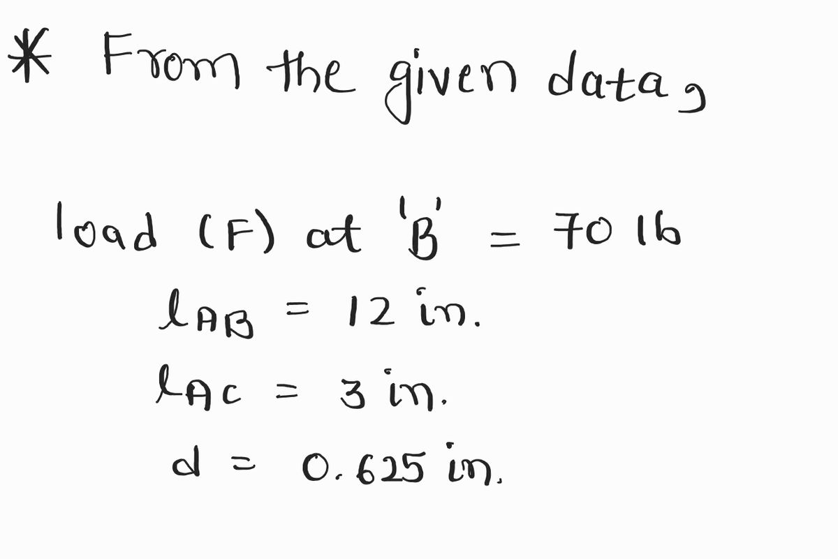
Force apply at point B is 70lb
Distacen from Point A to B is 12 in or 1 feet long
Distacen from Point A to C is 3 in
Handle diameter 0.625 in

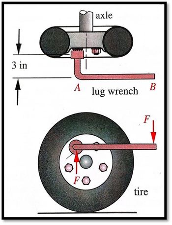
Transcribed Image Text:### How to Use a Lug Wrench
This educational image explains the application of a lug wrench when changing a tire and provides a clear understanding of its mechanics.
#### Diagram Description:
1. **Side View Diagram:**
- **Axle:** The central rod around which the wheel rotates.
- **Lug Wrench:** The tool used for loosening and tightening the lug nuts. It is depicted here in pink and has a handle labeled from point A to point B.
- **Distance Measurement:** The vertical distance from the center of the axle to the lug wrench handle (point B) is marked as 3 inches.
2. **Front View Diagram:**
- **Tire:** The round, black component that makes contact with the road and surrounds the wheel.
- **Lug Wrench Positioning:** The lug wrench is shown inserted into a lug nut on the tire.
- **Force (F):** The downward force applied at point B on the handle of the lug wrench, necessary for turning the lug nut.
The diagram effectively illustrates the principle of leverage used in turning the lug nuts with the lug wrench. By applying force at the end of the wrench (point B), the user generates sufficient torque to loosen or tighten the nuts, facilitating easier tire changes.
Expert Solution
arrow_forward
Step 1: Given data
For the solution refer below images.

- Find F.B.D. and shear and bending diagrams for portions AB and BC.
- Find stress tensor at A.
Step by stepSolved in 5 steps with 7 images

Knowledge Booster
Learn more about
Need a deep-dive on the concept behind this application? Look no further. Learn more about this topic, mechanical-engineering and related others by exploring similar questions and additional content below.Similar questions
- Calcuate torsion From Point A to Point C, Calcuate Bending From Point A to Point B and Point A to Point C. Draw a FBD from point A to point B and another for point A to C indicating what stresses are been calculate. Use the stress tensor and stress cube to Indicate what forces are acting at point A. Force apply at point B is 70lb Distacen from Point A to B is 12 in or 1 feet long Distacen from Point A to C is 3 in Handle diameter 0.625 inarrow_forwardAs a way to check my workarrow_forwardQUESTION 4 Figure 3 below shows a vertical rod under its own weight. Find the displacement at A and stress distribution. Use E-100 MPa and weight per unit volume 0.06 N/cm³. Solve using two elements and comment on the stress distribution. 1.6 m 1m A Area = 2500 cm² 8 B Area = 1500 cm²arrow_forward
- solve d and e pleasearrow_forward3) Solve the plane stress problem using two-element model to find displacements and stresses. 15 kN 30 mm E-70 GPa Thickness - 10 mmarrow_forwardCalcuate Shear and Bending From Point A to Point B and Point A to Point C. Draw a FBD from point A to point B and another for point A to C indicating what stresses are been calculate. Use the stress tensor and stress cube to Indicate what forces are acting at point A. Force apply at point B is 70lb Distacen from Point A to B is 12 in or 1 feet long Distacen from Point A to C is 3 in Handle diameter 0.625 inarrow_forward
- I need help with the last 4 boxes.arrow_forwardThe state of stress at a point on an element of material is shown. Let sigmaX= 49.0 ksi, sigmaY= 17.0 ksi, and Txy= 11.0 ksi. Use this information to represent the principle state of stress and maximum in plane shear stress. Plot the mohr circle and state sigmaX' and sigmaY' and Tx'y' with unit. Also draw the state of stress on the rotated element.arrow_forwardFrom 3 forces, 2 bending moments and 1 toque acting on B, which ones are non zero, and the direction they are acting. Then indicate if they make shear or normal stress Draw 3-d stress state cust above plane aarrow_forward
- why the expert here wrote -200 cos 75 when Σ Fx = 0 , I understand all steps but how he got - 200 cos 75 ( for the force ) (how the angle is 75 ) can you please clarify for me this point please ...... because I did not got the angle 75 dgree for 200 N force can you draw a diagrm for me please to see how 75 dgree links to 200 Narrow_forwardFigure Part A Fuc= 0.97 5m HA 2m KN Determine the magnitude of the projected component of the F-5 kN force acting along the axis BC of the pipe. Suppose that a 3.1 m and b=4.4 m (Figure 1) Express your answer to three significant figures and include the appropriate units. Submit Previous Answers Request Answer X Incorrect; Try Again; 4 attempts remaining B ? a 1m 1 of 1arrow_forwardCalcuate torsion From Point A to Point C, Calcuate Bending From Point A to Point B and Point A to Point C. Draw a FBD from point A to point B and another for point A to C indicating what stresses are been calculate. Use the stress tensor and stress cube to Indicate what forces are acting at point A. Force apply at point B is 70lb Distacen from Point A to B is 12 in or 1 feet long Distacen from Point A to C is 3 in Handle diameter 0.625 inarrow_forward
arrow_back_ios
SEE MORE QUESTIONS
arrow_forward_ios
Recommended textbooks for you
 Elements Of ElectromagneticsMechanical EngineeringISBN:9780190698614Author:Sadiku, Matthew N. O.Publisher:Oxford University Press
 Mechanics of Materials (10th Edition)Mechanical EngineeringISBN:9780134319650Author:Russell C. HibbelerPublisher:PEARSON
 Thermodynamics: An Engineering ApproachMechanical EngineeringISBN:9781259822674Author:Yunus A. Cengel Dr., Michael A. BolesPublisher:McGraw-Hill Education
 Control Systems EngineeringMechanical EngineeringISBN:9781118170519Author:Norman S. NisePublisher:WILEY
 Mechanics of Materials (MindTap Course List)Mechanical EngineeringISBN:9781337093347Author:Barry J. Goodno, James M. GerePublisher:Cengage Learning
 Engineering Mechanics: StaticsMechanical EngineeringISBN:9781118807330Author:James L. Meriam, L. G. Kraige, J. N. BoltonPublisher:WILEY

Elements Of Electromagnetics
Mechanical Engineering
ISBN:9780190698614
Author:Sadiku, Matthew N. O.
Publisher:Oxford University Press

Mechanics of Materials (10th Edition)
Mechanical Engineering
ISBN:9780134319650
Author:Russell C. Hibbeler
Publisher:PEARSON

Thermodynamics: An Engineering Approach
Mechanical Engineering
ISBN:9781259822674
Author:Yunus A. Cengel Dr., Michael A. Boles
Publisher:McGraw-Hill Education

Control Systems Engineering
Mechanical Engineering
ISBN:9781118170519
Author:Norman S. Nise
Publisher:WILEY

Mechanics of Materials (MindTap Course List)
Mechanical Engineering
ISBN:9781337093347
Author:Barry J. Goodno, James M. Gere
Publisher:Cengage Learning

Engineering Mechanics: Statics
Mechanical Engineering
ISBN:9781118807330
Author:James L. Meriam, L. G. Kraige, J. N. Bolton
Publisher:WILEY