
Electric Motor Control
10th Edition
ISBN: 9781133702818
Author: Herman
Publisher: CENGAGE L
expand_more
expand_more
format_list_bulleted
Related questions
Question
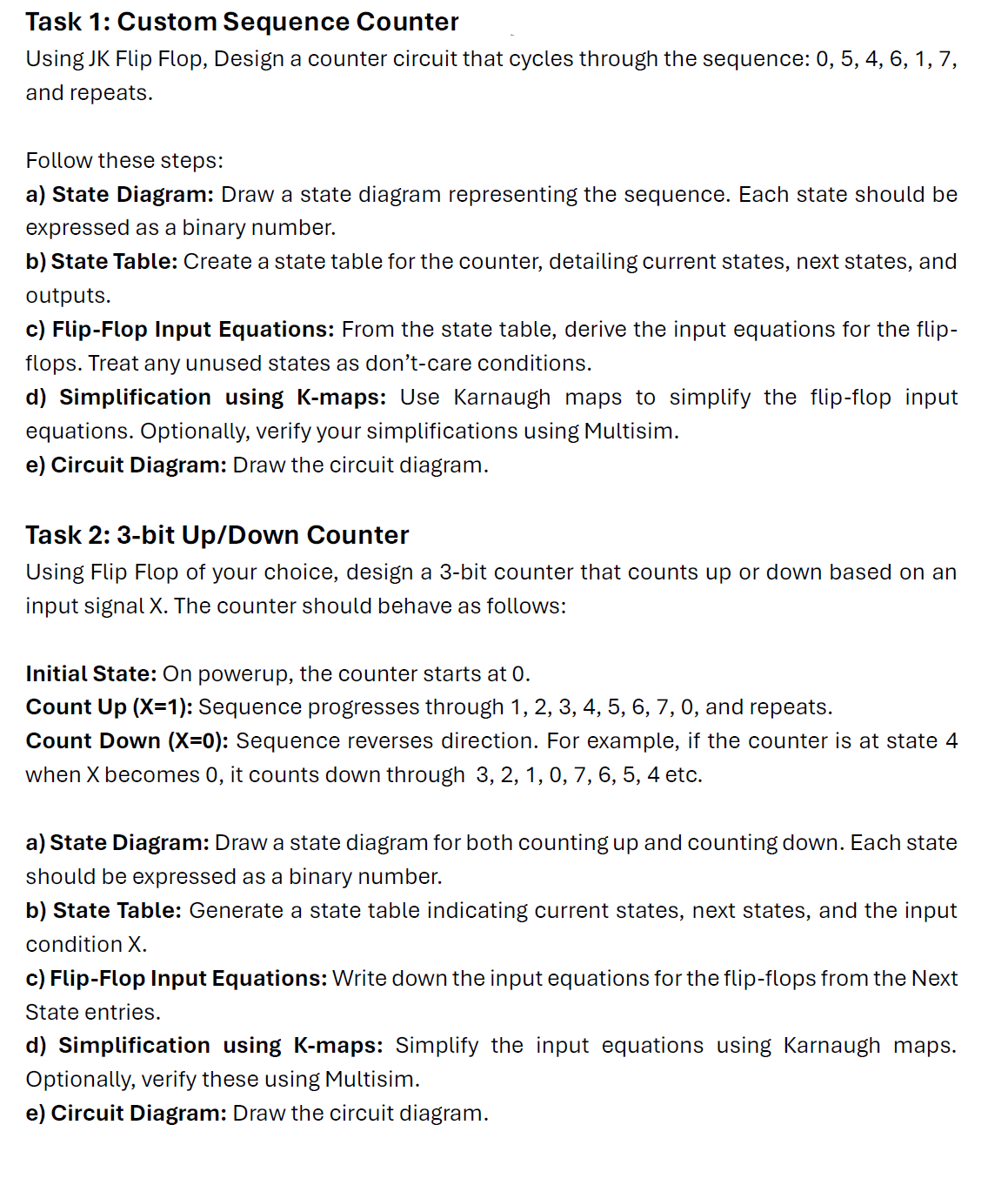

Transcribed Image Text:Task 1: Custom Sequence Counter
Using JK Flip Flop, Design a counter circuit that cycles through the sequence: 0, 5, 4, 6, 1, 7,
and repeats.
Follow these steps:
a) State Diagram: Draw a state diagram representing the sequence. Each state should be
expressed as a binary number.
b) State Table: Create a state table for the counter, detailing current states, next states, and
outputs.
c) Flip-Flop Input Equations: From the state table, derive the input equations for the flip-
flops. Treat any unused states as don't-care conditions.
d) Simplification using K-maps: Use Karnaugh maps to simplify the flip-flop input
equations. Optionally, verify your simplifications using Multisim.
e) Circuit Diagram: Draw the circuit diagram.
Task 2: 3-bit Up/Down Counter
Using Flip Flop of your choice, design a 3-bit counter that counts up or down based on an
input signal X. The counter should behave as follows:
Initial State: On powerup, the counter starts at 0.
Count Up (X=1): Sequence progresses through 1, 2, 3, 4, 5, 6, 7, 0, and repeats.
Count Down (X=0): Sequence reverses direction. For example, if the counter is at state 4
when X becomes 0, it counts down through 3, 2, 1, 0, 7, 6, 5, 4 etc.
a) State Diagram: Draw a state diagram for both counting up and counting down. Each state
should be expressed as a binary number.
b) State Table: Generate a state table indicating current states, next states, and the input
condition X.
c) Flip-Flop Input Equations: Write down the input equations for the flip-flops from the Next
State entries.
d) Simplification using K-maps: Simplify the input equations using Karnaugh maps.
Optionally, verify these using Multisim.
e) Circuit Diagram: Draw the circuit diagram.
Expert Solution
This question has been solved!
Explore an expertly crafted, step-by-step solution for a thorough understanding of key concepts.

Step by stepSolved in 2 steps with 2 images

Knowledge Booster

Similar questions
- Design a modulo-5 ripple (asynchronous) down-counter with D flip-flops and draw the corresponding logic circuit. (i) Build the state diagram and extract the state table(ii)Draw the logic circuit(iii) What is the maximum modulus of the counter?arrow_forward9. Analysis of Synchronous Counters, in the following figure, write the logic equation for each input of each flip-flop. Determine the next state for state 010,011,100,111 as Q2Q1Q0 sequence. FF0 FFI FF2 Ko K, K2 CLKarrow_forward5- a- what are the application of Flip – Flop. b- What is the difference between the Flip – Flop circuit and the other combinational logic circuits?arrow_forward
- 3.) The design size of the synchronous counter sequential (sequential) logic circuit. It will count from 0 to 9 and the son of your student number will not count decimals in two digits. A. List the process steps that you will apply in the design approach. Create the State Chart and State Chart. B. Design the sequential circuit using JK Flip-Flop. Explain each step. Show that it has performed the desired action. last digit student num: 0 4 " Not : I want the solution to contain tables and equations, and the electrical circuit resulting from tables and equations, as in the picture that I attached,And if possible, I want the solution on paper if possible.arrow_forwardReview Questions Question [4] For the given sequential circuit: a. What type of state machine is this circuit and why? b. Determine the flip-flop input equations and the output equations from the circuit. c. Derive the next-state equation for each flip-flop from its input equations. d. Derive the State table. e. Derive the State Graph. Determine the state sequence and output sequence if the initial state is So and the input sequence is X= 01100 B B KA CK JA KB CK to Clock Clock X" X- X' A B'arrow_forwardDesign Master-Slave Flip Flop circuit diagram and write a short description.arrow_forward
- 9 Using D flip-flops, (a) Design a counter with the following repeated binary sequence: 0, 1, 2, 4, 6. (b) Draw the logic diagram of the counter. (c) Design a counter with the following repeated binary sequence: 0, 2, 4, 6, 8. (d) Draw the logic diagram of the counter.arrow_forwardDesign an Octal Counter with D flip-flops. a) Draw the state diagram b) Draw the state table c) Draw the counter circuitarrow_forwardThe following statements describe the sequential circuits. Select all the TRUE statements. a The sequential circuits consist of a combinational circuit and storage elements. b The storage elements keep a binary bit even though the circuit power is gone. c Only the current input determines the outputs of sequential logic circuits. d The flip-flop is controlled by signal levels.arrow_forward
- Design a modulo-11 ripple (asynchronous) up-counter with negative edge-triggered T flip-flops and draw the corresponding logic circuit. (I)Build the state diagram and extract the state table (II)Draw the logic circuit (III)What is the maximum modulus of the counter?arrow_forwardDesign a synchronous counter with the irregular binary count sequence shown in the state diagram in the nearby figure. Use (a) D flip-flops, and (b) J-K flip-flops. 6 4 2arrow_forwardShow complete steps of the problem properly and show the circuitarrow_forward
arrow_back_ios
SEE MORE QUESTIONS
arrow_forward_ios
Recommended textbooks for you