Introductory Circuit Analysis (13th Edition)
13th Edition
ISBN: 9780133923605
Author: Robert L. Boylestad
Publisher: PEARSON
expand_more
expand_more
format_list_bulleted
Question

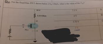
Transcribed Image Text:Q65. For the fixed-bias JFET shown below if Ip-10mA, what is the value of the Vps?
15 V
7.5 V
00+
VOS
1.5 K Ohm
901
A
4 V
B
5.75 V
C
5 V
Expert Solution
This question has been solved!
Explore an expertly crafted, step-by-step solution for a thorough understanding of key concepts.
Step by stepSolved in 2 steps

Knowledge Booster
Similar questions
- " A 2N5459 has VGS(off) = -8 v and IDSS = %3D 16mA. What is the drain current at the half cutoff point?arrow_forwarduo A:EV * ll. pluli ► b89f3244-f736-4021-901... PI EXPlain The effect of increasing The filter Capacitance on The outfut Voltage in The haif - wave rectifier and filber Circuit ? CS Scanned with CamScannerarrow_forwardplease label the questionsarrow_forward
- Create the Diode Characteristic Curve for this data values. Diode Voltage (VD) Diode Current (ID) 0.890904 9.109 0.884515 7.115 0.876023 5.124 0.86333 3.137 0.837654 1.162 0.793023 0.206975 0.779114 0.120885 0.754079 0.04592 0.695273 0.004727 0.599882 0.000118256 0.499998 0.000002487 0.4 5.2464E-08 0.3 1.39E-09 0.2 2.23008E-10 0.1 1.00568E-10 0 0 -0.1 -1.0011E-09 -0.2 -2.00211E-09 -0.3 -3.0031E-09 -0.4 -4.00411E-09 -0.5 -5.0051E-09 -0.6 -6.0061E-09 -0.7 -7.0071E-09 -0.8 -8.0081E-09 -0.9 -9.00911E-09 -1 -1.001E-08 -2 -2.002E-08 -4 -4.004E-08 -6 -6.006E-08 -8 -8.008E-08 -10 -1.001E-07 -20 -2.002E-07 -40 -4.004E-07 -60 -6.006E-07 -80 -8.008E-07 -100 -0.000001001 -200 -0.000002002 -300 -0.000003003 -400 -0.000004004 -500 -0.000005005arrow_forwardCT -2: Answer all partsarrow_forwardINCLUDE ALL THE DECIMALS.arrow_forward
- Q5) a) Calculate the minimum and the maximum input voltages that can be made by the given diode. The data sheet gives: Izmin = 2mA,Izmax=30mA, and Vz = 5 V. b) In which region of I-V characteristic does the diode operate ? Why? c) What is the main function for the given circuit? V1 =OV R1 10052 2 D1 1N5247Barrow_forward1. For a 60Hz, 9Vms AC input, with 250 Ohms load, determine VDc across the load, for FWR power supply, (show the required circuit). Draw the waveform on the load. 2. If C=200uf, filter capacitor is applied across the load: Calculate Vpp ripple and VDc, for the load. 3. Determine PIV on the diodes 4. If one of the diodes become open, what would be VDc and V, load. across the load, with & without capacitor. Draw the waveform on the fms,arrow_forwardWhat is the collector current for a C-E configurationwith a beta of 100 and a base current of 30 uA?A. 30 A B. 0.3 A C. 3mA D. 3MAarrow_forward
- Following the analysis applied to the half-wave rectifier with capacitor filter, show how to arrive at the output waveform for a center-tapped full-wave with filter capacitor.arrow_forwardA clamper circuit has 20 Vp-p. 100Hz square wave input voltage. The circuit consists of silicon diode IN4001 and 3V battery as shown in Figure 1 C. 0.1 µF D R Vi(t) 50 k2 Vo(t) 3 V Figure 1 a) Find the output voltage for all input voltages values. b) Sketch the output waveform, Vo(t).arrow_forwardDetermine the peak output voltage for the bridge rectifier in this figure. Assuming the practical model, what PIV rating is required for the diode? The transformer is specified to have a 12 Vrms secondary voltage for the standard 110 V across the primary. * D3 Di 110 V Vpsec) D2 RL D 10 k . Vp(out)= 14.6 V, PIV= 14.3 V O vp(out)= 16.5 V, PIV= 13.6 V Vp(out)= 13.6 V, PIV= 13.3 V O vp(out)= 15.6 V, PIV= 16.3 V ell elllarrow_forward
arrow_back_ios
SEE MORE QUESTIONS
arrow_forward_ios
Recommended textbooks for you
 Introductory Circuit Analysis (13th Edition)Electrical EngineeringISBN:9780133923605Author:Robert L. BoylestadPublisher:PEARSON
 Delmar's Standard Textbook Of ElectricityElectrical EngineeringISBN:9781337900348Author:Stephen L. HermanPublisher:Cengage Learning
 Programmable Logic ControllersElectrical EngineeringISBN:9780073373843Author:Frank D. PetruzellaPublisher:McGraw-Hill Education
 Fundamentals of Electric CircuitsElectrical EngineeringISBN:9780078028229Author:Charles K Alexander, Matthew SadikuPublisher:McGraw-Hill Education
 Electric Circuits. (11th Edition)Electrical EngineeringISBN:9780134746968Author:James W. Nilsson, Susan RiedelPublisher:PEARSON
 Engineering ElectromagneticsElectrical EngineeringISBN:9780078028151Author:Hayt, William H. (william Hart), Jr, BUCK, John A.Publisher:Mcgraw-hill Education,

Introductory Circuit Analysis (13th Edition)
Electrical Engineering
ISBN:9780133923605
Author:Robert L. Boylestad
Publisher:PEARSON

Delmar's Standard Textbook Of Electricity
Electrical Engineering
ISBN:9781337900348
Author:Stephen L. Herman
Publisher:Cengage Learning

Programmable Logic Controllers
Electrical Engineering
ISBN:9780073373843
Author:Frank D. Petruzella
Publisher:McGraw-Hill Education

Fundamentals of Electric Circuits
Electrical Engineering
ISBN:9780078028229
Author:Charles K Alexander, Matthew Sadiku
Publisher:McGraw-Hill Education

Electric Circuits. (11th Edition)
Electrical Engineering
ISBN:9780134746968
Author:James W. Nilsson, Susan Riedel
Publisher:PEARSON

Engineering Electromagnetics
Electrical Engineering
ISBN:9780078028151
Author:Hayt, William H. (william Hart), Jr, BUCK, John A.
Publisher:Mcgraw-hill Education,