Introductory Circuit Analysis (13th Edition)
13th Edition
ISBN: 9780133923605
Author: Robert L. Boylestad
Publisher: PEARSON
expand_more
expand_more
format_list_bulleted
Question

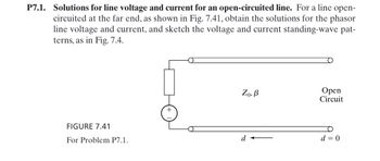
Transcribed Image Text:P7.1. Solutions for line voltage and current for an open-circuited line. For a line open-
circuited at the far end, as shown in Fig. 7.41, obtain the solutions for the phasor
line voltage and current, and sketch the voltage and current standing-wave pat-
terns, as in Fig. 7.4.
FIGURE 7.41
For Problem P7.1.
Zo, B
Open
Circuit
+
d
d = 0
Expert Solution
This question has been solved!
Explore an expertly crafted, step-by-step solution for a thorough understanding of key concepts.
Step by stepSolved in 2 steps with 3 images

Knowledge Booster
Similar questions
- For the circuit shown in Figure 7.4, determine apparent power S, real power P, reactive power Qand power factor PF. Also, draw the power triangle. The source is 120 volts.arrow_forwardThanksarrow_forwardFor the circuit shown in Figure 7.5, determine apparent power S, real power P, reactive power Qand power factor PF. The source is 90 volts, XL = j30 Ω, R = 50 Ω.arrow_forward
- Each phase of a transmission line is a bundle of 4 conductors that form a square with all sides equal to d=33 cm. Each conductor is stranded and has GMR = 0.5 cm. Find GMR of the bundle to be used in inductance calculations. Express your answer in cm with 2 digits after decimal pointarrow_forward1- A single phase line has two parallel conductors 3m apart. The radius of each conductor is 1.2 cm. calculate the loop inductance per km of the line. 2- A single phase line has two parallel conductors 4m apart. The radius of each conductor is 2m. Calculate the capacitance per km of the line.arrow_forwardQ2: A single-phase transmission line consisting of two conductors, the radius of each conductor is 0.4 cm, the distance between the conductors is three and half meters and the height above ground is eight meter. The capacitance in µF/km without effect -1 of ground is إجابتك The capacitance in µF/km with effect of -2 ground isarrow_forward
- Fill in the table for a correctly wired duplex outlet (U.S. National Electric Code standards for voltage PARAMETER EQUATION and frequency). Note the used of double- subscript notation. You can assume a 0° phase reference for Vba(t). Vba(t) Vea(t) Vbe(t) Vba (Peak Phasor) Vea (Peak Phasor) Vbc (Peak Phasor) Vba (RMS Phasor) Vea (RMS Phasor) Vbc (RMS Phasor) A Carrow_forwardPlease solve in detail to understandarrow_forwardExample 8.11. Each line of a 3-phase system is suspended by a string of 3 indentical insulators of self-capacitance C farad. The shunt capacitance of connecting metal work of each insulator is 0.2 C to earth and 0-1 C to line. Calculate the string efficiency of the system if a guard ring increases the capacitance to the line of metal work of the lowest insulator to 0.3 C.arrow_forward
- If you double the impedance of a transmission line you will double the inductance per unit length. T or F. Can you explain why????arrow_forwardPlease provide Handwritten answerarrow_forwardFor the circuit shown in Figure 7.6, determine apparent power S, real power P, reactive power Qand power factor PF. Also, draw the power triangle. The source is 240 volts, XC = −j200 Ω,R = 75 Ω.arrow_forward
arrow_back_ios
SEE MORE QUESTIONS
arrow_forward_ios
Recommended textbooks for you
 Introductory Circuit Analysis (13th Edition)Electrical EngineeringISBN:9780133923605Author:Robert L. BoylestadPublisher:PEARSON
 Delmar's Standard Textbook Of ElectricityElectrical EngineeringISBN:9781337900348Author:Stephen L. HermanPublisher:Cengage Learning
 Programmable Logic ControllersElectrical EngineeringISBN:9780073373843Author:Frank D. PetruzellaPublisher:McGraw-Hill Education
 Fundamentals of Electric CircuitsElectrical EngineeringISBN:9780078028229Author:Charles K Alexander, Matthew SadikuPublisher:McGraw-Hill Education
 Electric Circuits. (11th Edition)Electrical EngineeringISBN:9780134746968Author:James W. Nilsson, Susan RiedelPublisher:PEARSON
 Engineering ElectromagneticsElectrical EngineeringISBN:9780078028151Author:Hayt, William H. (william Hart), Jr, BUCK, John A.Publisher:Mcgraw-hill Education,

Introductory Circuit Analysis (13th Edition)
Electrical Engineering
ISBN:9780133923605
Author:Robert L. Boylestad
Publisher:PEARSON

Delmar's Standard Textbook Of Electricity
Electrical Engineering
ISBN:9781337900348
Author:Stephen L. Herman
Publisher:Cengage Learning

Programmable Logic Controllers
Electrical Engineering
ISBN:9780073373843
Author:Frank D. Petruzella
Publisher:McGraw-Hill Education

Fundamentals of Electric Circuits
Electrical Engineering
ISBN:9780078028229
Author:Charles K Alexander, Matthew Sadiku
Publisher:McGraw-Hill Education

Electric Circuits. (11th Edition)
Electrical Engineering
ISBN:9780134746968
Author:James W. Nilsson, Susan Riedel
Publisher:PEARSON

Engineering Electromagnetics
Electrical Engineering
ISBN:9780078028151
Author:Hayt, William H. (william Hart), Jr, BUCK, John A.
Publisher:Mcgraw-hill Education,