
Fundamentals of Geotechnical Engineering (MindTap Course List)
5th Edition
ISBN: 9781305635180
Author: Braja M. Das, Nagaratnam Sivakugan
Publisher: Cengage Learning
expand_more
expand_more
format_list_bulleted
Related questions
Question
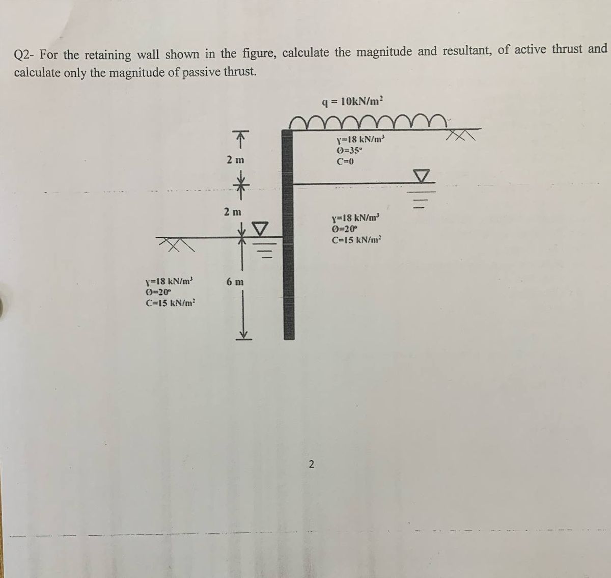

Transcribed Image Text:Q2- For the retaining wall shown in the figure, calculate the magnitude and resultant, of active thrust and
calculate only the magnitude of passive thrust.
q = 10kN/m²
不
2 m
y-18 kN/m³
0=35°
C=0
*
2 m
y=18 kN/m³
0=20°
6 m
C=15 kN/m²
y=18 kN/m³
0-20°
C=15 kN/m²
2
Expert Solution
This question has been solved!
Explore an expertly crafted, step-by-step solution for a thorough understanding of key concepts.

Step by stepSolved in 2 steps

Knowledge Booster

Similar questions
- A braced wall is shown in Figure 14.20. Given: H = 7 m, naH = 2.8 m, =30, =20, = 18 kN/m3, and c = 0. Determine the active thrust, Pa, on the wall using the general wedge theory. Figure 14.20arrow_forwardRefer to Figure 15.27a. For the braced cut, H = 6 m, Hs = 2 m, s = 16.2 kN/m3, angle of friction of sand, s=34, Hc = 4 m, c = 17.5 kN/m3, and the unconfined compression strength of the clay layer, qu = 68 kN/m2. a. Estimate the average cohesion, cav, and the average unit weight, av, for development of the earth pressure envelope. b. Plot the earth pressure envelope. FIG. 15.27 Layered soils in braced cutsarrow_forwardRepeat Problem 10.12 for q = 700 kN/m2, B = 8 m, and z = 4 m. In this case, point A is located below the centerline under the strip load. 10.12 Refer to Figure 10.43. A strip load of q = 1450 lb/ft2 is applied over a width with B = 48 ft. Determine the increase in vertical stress at point A located z = 21 ft below the surface. Given x = 28.8 ft. Figure 10.43arrow_forward
- Refer to Figure P3.3. Use Eqs. (3.10) and (3.11) to determine the variation of OCR and preconsolidation pressure c. FIGURE P3.3arrow_forwardThe cross section of a braced cut supporting a sheet pile installation in a clay soil is shown in Figure 14.22. Given: H = 12 m, clay = 17.9 kN/m3, = 0, c = 75 kN/m2, and the center-to-center spacing of struts in plan view, s = 3 m. a. Using Pecks empirical pressure diagrams, draw the earth-pressure envelope. b. Determine the strut loads at levels A, B, and C.arrow_forwardIn Problem 16.3, if there was a surcharge of 20 kN/m2 at the ground level, what would be the total horizontal normal stresses at A and B? Use the results from Problem 16.3. 16.3 The soil profile at a site is shown Figure P16.3. Find the total horizontal normal stresses at A and B, assuming at-rest conditions.arrow_forward
- For the same line loads given in Problem 10.8, determine the vertical stress increase, z, at a point located 4 m below the line load, q2. Refer to Figure 10.41. Determine the vertical stress increase, z, at point A with the following values: q1 = 110 kN/m, q2 = 440 kN/m, x1 = 6 m, x2 = 3 m, and z = 4 m. Figure 10.41arrow_forwardFor the data given in this problem, determine the magnitude of the active thrust on the wall retaining a c soil, using the procedure discussed in Section 16.10. Given H = 15.0 ft, c = 100 lb/ft2, = 26, = 115 lb/ft3, kv = 0, and kh = 0.3.arrow_forwardThe elevation and plan of a bracing system for an open cut in sand are shown in Figure 14.21. Using Pecks empirical pressure diagrams, determine the design strut loads. Given: sand = 18 kN/m3, ' = 38, x = 3 m, z = 1.25 m, and s = 3 m.arrow_forward
- Figure 15.53 below shows a cantilever sheet pile driven into a granular soil where the water table is 2 m below the top of the sand. The properties of thesand are: ' = 40, m = 17.5 kN/m3, and sat = 19 kN/m3. It is proposed toexcavate to a depth of 6 m below the ground level. Determine the depth towhich the sheet pile mast be driven, using the net lateral pressure diagram. Fig. 15.53arrow_forwardRefer to the flexible loaded rectangular area shown in Figure 10.47. Using Eq. (10.36), determine the vertical stress increase below the center of the loaded area at depths z = 3, 6, 9, 12, and 15 m. Figure 10.47arrow_forward
arrow_back_ios
arrow_forward_ios
Recommended textbooks for you
- Fundamentals of Geotechnical Engineering (MindTap...Civil EngineeringISBN:9781305635180Author:Braja M. Das, Nagaratnam SivakuganPublisher:Cengage Learning
 Principles of Foundation Engineering (MindTap Cou...Civil EngineeringISBN:9781305081550Author:Braja M. DasPublisher:Cengage Learning
 Principles of Geotechnical Engineering (MindTap C...Civil EngineeringISBN:9781305970939Author:Braja M. Das, Khaled SobhanPublisher:Cengage Learning
  Principles of Foundation Engineering (MindTap Cou...Civil EngineeringISBN:9781337705028Author:Braja M. Das, Nagaratnam SivakuganPublisher:Cengage Learning
Fundamentals of Geotechnical Engineering (MindTap...
Civil Engineering
ISBN:9781305635180
Author:Braja M. Das, Nagaratnam Sivakugan
Publisher:Cengage Learning
Principles of Foundation Engineering (MindTap Cou...
Civil Engineering
ISBN:9781305081550
Author:Braja M. Das
Publisher:Cengage Learning
Principles of Geotechnical Engineering (MindTap C...
Civil Engineering
ISBN:9781305970939
Author:Braja M. Das, Khaled Sobhan
Publisher:Cengage Learning
Principles of Foundation Engineering (MindTap Cou...
Civil Engineering
ISBN:9781337705028
Author:Braja M. Das, Nagaratnam Sivakugan
Publisher:Cengage Learning