
Principles of Foundation Engineering (MindTap Course List)
8th Edition
ISBN: 9781305081550
Author: Braja M. Das
Publisher: Cengage Learning
expand_more
expand_more
format_list_bulleted
Related questions
Question
Please answer the questions in the picture. Thank you for your help. For part B use the Second Picture.
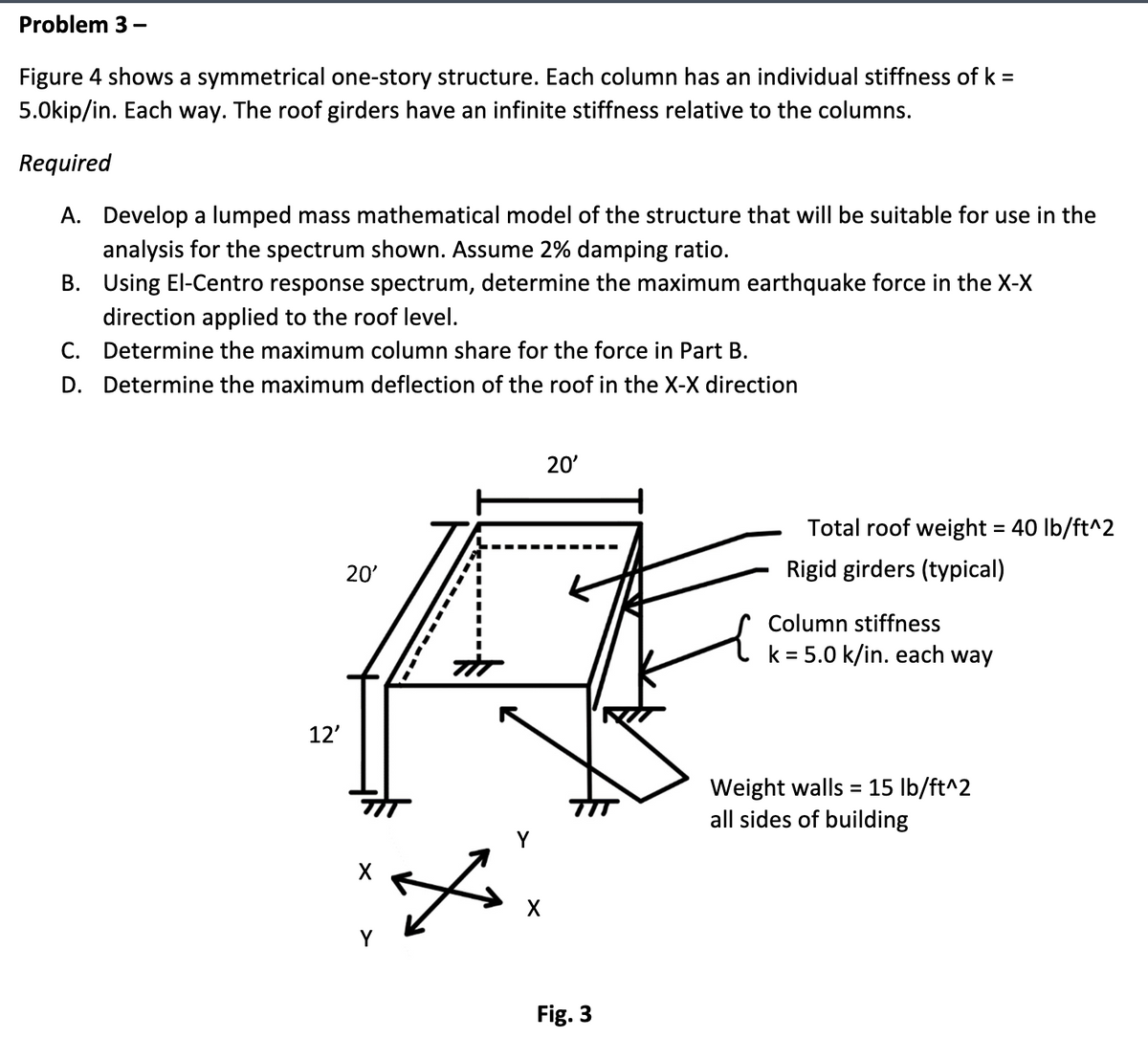

Transcribed Image Text:Problem 3 -
Figure 4 shows a symmetrical one-story structure. Each column has an individual stiffness of k =
5.Okip/in. Each way. The roof girders have an infinite stiffness relative to the columns.
Required
A. Develop a lumped mass mathematical model of the structure that will be suitable for use in the
analysis for the spectrum shown. Assume 2% damping ratio.
B. Using El-Centro response spectrum, determine the maximum earthquake force in the X-X
direction applied to the roof level.
C. Determine the maximum column share for the force in Part B.
D. Determine the maximum deflection of the roof in the X-X direction
12'
20'
X
20'
Fig. 3
Total roof weight = 40 lb/ft^2
Rigid girders (typical)
Column stiffness
k =5.0 k/in. each way
Weight walls = 15 lb/ft^2
all sides of building

Transcribed Image Text:RESPONSE SPECTRUM
IMPERIAL VALLEY EARTHQUAKE
MAY 18, 1940 - 2037 PST
IIIA001 40.001.0 EL CENTRO SITE IMPERIAL VALLEY IRRIGATION DISTRICT COMP SOOE
DAMPING VALUES ARE O. 2. 5. 10 AND 20 PERCENT OF CRITICAL
400
200
F80
Acceleration, g
80
60
40
8884
100
20
20
086
4
VELOCITY (in./sec)
.8
201
02
800
006
004
002
الله
2
86
Displacement, in.
-20
400
008-
600
400
200
60
200
100
80
60
-800
40
20
20
006
004+
10
986
F2000
4
2
0013
8000
0006
0004
.8
.6
2
4
6810
PERIOD (secs)
.1
.04 .06.08.1
.2
4 .6.81
20
4
2
20
20
Expert Solution
This question has been solved!
Explore an expertly crafted, step-by-step solution for a thorough understanding of key concepts.

Step by stepSolved in 2 steps with 8 images

Knowledge Booster

Similar questions
- EB and FG are two planes inside a soil element ABCD as shown in Figure 10.50. Stress conditions on the two planes are Plane EB: EB = 25 kN/m2; EB = +10 kN/m2 Plane FG: FG = 10 kN/m2; FG = 5 kN/m2 (Note: Mohrs circle sign conventions for stresses are used above) Given ; = 25, determine: a. The maximum and minimum principal stresses b. The angle between the planes EB and FG c. The external stresses on planes AB and BC that would cause the above internal stresses on planes EB and FGarrow_forwardTwo line loads q1 and q2 of infinite lengths are acting on top of an elastic medium, as shown in Figure P8.6. Find the vertical stress increase at A.arrow_forwardRefer to Figure 10.43. A strip load of q = 1450 lb/ft2 is applied over a width with B = 48 ft. Determine the increase in vertical stress at point A located z = 21 ft below the surface. Given x = 28.8 ft. Figure 10.43arrow_forward
- The soil profile at a site is shown Figure P16.3. Find the total horizontal normal stresses at A and B, assuming at-rest conditions.arrow_forwardUse Eq. (6.14) to determine the stress increase () at z = 10 ft below the center of the area described in Problem 6.5. 6.5 Refer to Figure 6.6, which shows a flexible rectangular area. Given: B1 = 4 ft, B2 = 6 ft, L1, = 8 ft, and L2 = 10 ft. If the area is subjected to a uniform load of 3000 lb/ft2, determine the stress increase at a depth of 10 ft located immediately below point O. Figure 6.6 Stress below any point of a loaded flexible rectangular areaarrow_forwardRepeat Problem 10.12 for q = 700 kN/m2, B = 8 m, and z = 4 m. In this case, point A is located below the centerline under the strip load. 10.12 Refer to Figure 10.43. A strip load of q = 1450 lb/ft2 is applied over a width with B = 48 ft. Determine the increase in vertical stress at point A located z = 21 ft below the surface. Given x = 28.8 ft. Figure 10.43arrow_forward
- Refer to Figure 10.46. A flexible circular area of radius 6 m is uniformly loaded. Given: q = 565 kN/m2. Using Newmarks chart, determine the increase in vertical stress, z, at point A. Figure 10.46arrow_forwardRefer to Figure 10.42. Due to application of line loads q1 and q2, the vertical stress increase at point A is 58 kN/m2. Determine the magnitude of q2. Figure 10.42arrow_forwardRefer to Figure 8.24. Determine the vertical stress increase, , at point A with the following values: q1 = 100 kN/m x1 = 3 m z = 2 m q2 = 200 kN/m x2 = 2 m FIG. 8.24 Stress at a point due to two line loadsarrow_forward
- A point load of 1000 kN is applied at the ground level. Plot the variation of the vertical stress increase z with depth at horizontal distances of 1 m, 2 m, and 4 m from the load.arrow_forwardA 10 ft diameter flexible loaded area is subjected to a uniform pressure of 1200 lb/ft2. Plot the variation of the vertical stress increase beneath the center with depth z = 0 to 20 ft. In the same plot, show the variation beneath the edge of the loaded area.arrow_forwardA point load of 1000 kN is applied at the ground level. Plot the variation of the vertical stress increase Δσ with depth at horizontal distance of 1 m, 2 m, and 4 m from the load.arrow_forward
arrow_back_ios
SEE MORE QUESTIONS
arrow_forward_ios
Recommended textbooks for you
- Principles of Foundation Engineering (MindTap Cou...Civil EngineeringISBN:9781305081550Author:Braja M. DasPublisher:Cengage Learning
 Principles of Geotechnical Engineering (MindTap C...Civil EngineeringISBN:9781305970939Author:Braja M. Das, Khaled SobhanPublisher:Cengage Learning
 Principles of Foundation Engineering (MindTap Cou...Civil EngineeringISBN:9781337705028Author:Braja M. Das, Nagaratnam SivakuganPublisher:Cengage Learning
  Fundamentals of Geotechnical Engineering (MindTap...Civil EngineeringISBN:9781305635180Author:Braja M. Das, Nagaratnam SivakuganPublisher:Cengage Learning
 Materials Science And Engineering PropertiesCivil EngineeringISBN:9781111988609Author:Charles GilmorePublisher:Cengage Learning
 Engineering Fundamentals: An Introduction to Engi...Civil EngineeringISBN:9781305084766Author:Saeed MoaveniPublisher:Cengage Learning
Principles of Foundation Engineering (MindTap Cou...
Civil Engineering
ISBN:9781305081550
Author:Braja M. Das
Publisher:Cengage Learning
Principles of Geotechnical Engineering (MindTap C...
Civil Engineering
ISBN:9781305970939
Author:Braja M. Das, Khaled Sobhan
Publisher:Cengage Learning
Principles of Foundation Engineering (MindTap Cou...
Civil Engineering
ISBN:9781337705028
Author:Braja M. Das, Nagaratnam Sivakugan
Publisher:Cengage Learning
Fundamentals of Geotechnical Engineering (MindTap...
Civil Engineering
ISBN:9781305635180
Author:Braja M. Das, Nagaratnam Sivakugan
Publisher:Cengage Learning
Materials Science And Engineering Properties
Civil Engineering
ISBN:9781111988609
Author:Charles Gilmore
Publisher:Cengage Learning
Engineering Fundamentals: An Introduction to Engi...
Civil Engineering
ISBN:9781305084766
Author:Saeed Moaveni
Publisher:Cengage Learning