
Power System Analysis and Design (MindTap Course List)
6th Edition
ISBN: 9781305632134
Author: J. Duncan Glover, Thomas Overbye, Mulukutla S. Sarma
Publisher: Cengage Learning
expand_more
expand_more
format_list_bulleted
Related questions
Question
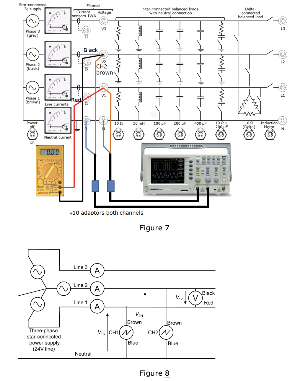

Transcribed Image Text:Star-connected
3+ supply
Phase 3
(grey)
Filtered
Current Voltage
sensors 1V/A
Ө
13
V3
10
Phase 2
(black)
Black
Phase 1
(brown)
Red
Line currents
11
Power
Neutral current
0.00
се
Three-phase
star-connected
power supply
(24V line)
V2
CH2
brown
V1
Star-connected balanced loads
with neutral connection
HEA› HFA³· HEA
Im . m 1. m
www
10 Ω
30 mH
100 μF
200 µF
400 μF
+10 adaptors both channels
Line 3
A
Line 2
A
Line 1
A
Neutral
ww
www
Figure 7
00000
·
Delta-
connected
balanced load
102+
200 µF
10 Ω
(Delta)
Black
V12
V
Red
V2N
Brown
Brown
VIN CH1 (N)
CH2N
Blue
Blue
Figure 8
L3
Induction
Motor
L2
L1

Transcribed Image Text:+
Phase voltage
Line and phase voltage measurements
Phase voltage V1N, potential
difference of line 1 with respect to
13.2V
(phase 1)
neutral (rms)
Phase voltage
Phase voltage V2N, potential
-6.8ms
(phase 2)
difference of line 2 with respect to
neutral (rms)
Line voltage
Line-to-line (line) voltage
23.8V
(phases 1-2)
(rms), V12 from meter
Time difference for V12
*Phase angle for V12 rel to V1N
1.8ms
32.8deg
*Calculate later to allow you to complete phasor diagram
Draw accurately and to scale the phasor diagram showing how the
rms magnitudes and phases of the line voltages V12, V23 and V31
relate to the phase voltages V1N, V2N and V3N, and use your diagram
to show specifically (using your measured magnitude and phase of
V12) that V12 = V1N- V2N
Expert Solution
This question has been solved!
Explore an expertly crafted, step-by-step solution for a thorough understanding of key concepts.

Step by stepSolved in 2 steps

Knowledge Booster

Similar questions
- Find the following : 1.Ripple Voltage (vpp) 2. Zero-to peak ripple(Vop) 3.secondary winding of the transformer high line and low linearrow_forwardProblem 1 - Series en Parallel AC networks [19] Look at the circuit in Figure 1 and determine the following: (a) Total Admittance. (b) Total Impedance. (c) Total Current (l:). (d) Current (I1) through impedance Z2. (e) Current (12) through impedance Z3. (f) Current (I3) through impedance Z4. (g) Is this an inductive or capacitive circuit? A. B Zs 220V;50HZ Figure 1 (h) Voltage across Z1. (i) Voltage across A and B. G) Voltage across Zs. Z1 = 3 + j5 ohm Z2 = 10 + jo ohm Z3 = 5 + j15 ohm Z4 = 10 – j30 ohm Zs = 20 – j30 ohm Admittance and Impedance in rectangular notation. All currents and voltage in polar notation. Take voltage as reference.arrow_forwarda) List the four short-circuit faults in three-phase power systems in order of frequency of occurrence, b) In the three-phase system shown in Figure As3.1, phase a is on no load and phase b and c are short-circuit to ground. I =0 Figure As3.1 The following currents are given:/, = 91.65 < 160.9°; In = 60.00 < 90° Find the symmetrical components of the current la1, laz and lao c) Write the MATLAB Script for (b) above.arrow_forward
- Analyse several voltage and current situations in different loading scenarios in a simplified radial (transformer to consumption) medium-voltage power system example. There are only 2 nodes in the 35 kV line – node 0 from the 110/35 kV and node 1 with one consumer. The physical characteristics of the line and the loading scenarios are individualized for each student – please see the attached file Excel “WM9P3 Task1 data” for your particular data set. Briefly reflect on the complexity of the calculations for known input or output voltage, as well as for fixed or voltage-dependent consumption in this simple power system model. Analyse and discuss the sensitivity of the voltage drop [in % of amplitude and the degrees of phase] with respect to the current level [in %] and to the power factor.arrow_forwardIn the above figure, a single line model of a three-phase power system is given. Base power 50MVA, base voltage 13.8kV according to its value, a) Per-unit values of power system circuit elements according to the given base power and base voltage values. calculate. b) The perunit you calculate by drawing the equivalent impedance circuit for one phase of the power system given in the figure. show on the values.arrow_forwardConsider the single-Line diagram of a power system shown in Figure 3.42 with equipment ratings given: Generator G1: 50MVA,13.2kV,x=0.15p.u. Generator G2: 20MVA,13.8kV,x=0.15p.u. Three-phase -Y transformer T1: 80MVA,13.2/165YkV,X=0.1p.u. Three-phase Y- transformer T2: 40MVA,165Y/13.8kV,X=0.1p.u. Load: 40MVA,0.8PFlagging,operatingat150kV Choose a base of 100 MVA for the system and 132-kV base in the transmission-line circuit. Let the load be modeled as a parallel combination of resistance and inductance. Neglect transformer phase shifts. Draw a per-phase equivalent circuit of the system showing all impedances in per unit.arrow_forward
- High voltage engineering subjectarrow_forwardA 30-MVA alternator with 15% reactance is connected to a bus bar. A second alternator rated 25-MVA with 10% reactance is also connected through a 10% bus bar reactor to the same bus bar. Both of these reactances are based on 25 MVA. If a feeder taken out from the bus bars through a circuit breaker develops a 3-phase fault, what should be the appropriate MVA rating of the circuit breaker?(325 MVA)arrow_forwardFor transferring electrical power at 220 kV, six conductors of ACSR Drake constitute a 60Hz double circuit three phase line arranged as shown below. The vertical spacing between consecutive conductors is 14ft; the longer horizontal distance is 32ft whereas the shorter horizontal distance is 25ft. a. Find the inductance per phase per mile and the inductive reactance per phase in ohms per mile. b. Find the capacitive reactance to neutral in ohm-miles. c. Find the resistance per phase per mile in ohms per miles. d. If the length of the line is 90 miles then draw an equivalent circuit of the line and analyse the open circuit and short circuit performance of the line. e. Find the maximum power we can transmit over the line. f. If the line is delivering power to a load of 20MW at 0.8 power factor lagging then find the voltage at the receiving end of the line. Also, Determine the voltage regulation, losses and efficiency of the line. g. If a fixed shunt compensation of 3 MVAr is attached at…arrow_forward
- Q2. The single-line diagram of a simple three-bus power system is shown in Figure-2. Each generator is represented by an emf behind the sub-transient reactance. All impedances are expressed in per unit on a common MVA base. All resistances and shunt capacitances are neglected. The generators are operating on no load at their rated voltage with their emfs in phase. A three-phase fault occurs at bus 3 through a fault impedance of Zf = j0.19 per unit. (i) Using Th'evenin's theorem, obtain the impedance to the point of fault and the fault current in (ii) Determine the bus voltages per unit. ) j0.05 j0.075 j0.75 2 j0.30 j0.45 Figure-2: Single line diagram of the power system network for Q2 3arrow_forwardA short transmission line connects a step-up transformer on the source side with a series impedance of j0.5 ohms (referred to the primary) to a step-down transformer on the load side with a series impedance of 50 ohms (referred to the primary). The turn ratio of the step-up transformer is 1:10 and a no-load primary voltage of 23 (line-to-line) kV. The step-down transformer has a turn ratio of 35:2 and it has a Y-connected, balanced load of 0.490 +j 0.0816 ohms connected to its secondary side. Assuming an ideal transmission line, compute the load voltage (line-to-neutral).arrow_forwardnot use ai pleasearrow_forward
arrow_back_ios
SEE MORE QUESTIONS
arrow_forward_ios
Recommended textbooks for you
- Power System Analysis and Design (MindTap Course ...Electrical EngineeringISBN:9781305632134Author:J. Duncan Glover, Thomas Overbye, Mulukutla S. SarmaPublisher:Cengage Learning
Power System Analysis and Design (MindTap Course ...
Electrical Engineering
ISBN:9781305632134
Author:J. Duncan Glover, Thomas Overbye, Mulukutla S. Sarma
Publisher:Cengage Learning