Introductory Circuit Analysis (13th Edition)
13th Edition
ISBN: 9780133923605
Author: Robert L. Boylestad
Publisher: PEARSON
expand_more
expand_more
format_list_bulleted
Question
Provide complete solution of the given problem in the image.

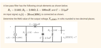
Transcribed Image Text:A low pass filter has the following circuit elements as shown below.
R₁ = 2.5k; R₂ = 2.0kN; L = 500mH; and C = 2.5µF
An input signal, v(t) = 20cos(400t), is connected as shown.
Determine the RMS value of the output voltage, Vo,RMS, in volts rounded to two decimal places.
L= 500m H
R₂ 2.0K -oms
R₁ 2.5K ohms
vi(t) = 20cos(4001)
C2.5uF
V₁(RMS)=?
Expert Solution
This question has been solved!
Explore an expertly crafted, step-by-step solution for a thorough understanding of key concepts.
Step by stepSolved in 2 steps with 1 images

Knowledge Booster
Similar questions
- Identify the reason for a nonsinusoidal signal being distorted when it passes through a filter. -The distortion occurs because harmonics are removed or rejected, leaving a different waveshape. -The distortion occurs because harmonics are synchronized, leaving a different waveshape. -The distortion occurs because the signal is modulated, leaving a different waveshape. -The distortion occurs because harmonics are added in the filter, leaving a different waveshape.arrow_forwardAn RC low-pass filter is shown in the figure. Its purpose is to attenuate higher frequencies while allowing lower frequencies to pass through. A 960-Hz sine-wave signal with rms amplitude of Vrms = 1.9 V is fed into the filter. The values of the components are R = 120 Ω and C = 0.64 μF and Vout-rms = 1.724 V. By what angle, in degrees, does the output voltage lag the input voltage?arrow_forwardAC Circuits An RC high-pass filter is shown in the figure. Its purpose is to attenuate lower frequencies while allowing higher frequencies to pass through. A 1020-Hz sine-wave signal with rms amplitude of Vrms = 2.5 V is fed into the filter. The values of the components are R = 140 Ω and C = 0.76 μF. Part (a) Find the output rms voltage, in volts.arrow_forward
- An RL low-pass filter is shown in the figure. Its purpose is to attenuate higher frequencies while allowing lower frequencies to pass through. A 920-Hz sine-wave signal with rms amplitude of Vrms = 2.1 V is fed into the filter. The values of the components are R = 0.57 Ω and L = 110 μH. A) Find the output rms voltage, in volts. B) By what angle, in degrees, does the output voltage lag the input voltage?arrow_forwardI need the answer as soon as possiblearrow_forwardAn RL high-pass filter is shown in the figure. Its purpose is to attenuate lower frequencies while allowing higher frequencies to pass through. A 1140-Hz sine-wave signal with rms amplitude of Vrms = 2.8 V is fed into the filter. The values of the components are R = 0.95 Ω and L = 180 μH. a) Find the output rms voltage, in volts. b) By what angle, in degrees, does the output voltage lead the input voltage?arrow_forward
- H.W: A resistor of resistance R=1000 2is maintained at 17 °C and it shunted by 100 uH inductor. Determine the ms noise voltage across the inductor over a frequency bandwi dth of: Ans: 182 x10° volt Ans: 9.22 x10 volt Ans: 2.34 x10 volt i) 15.9 kHz ii) i) 159 kHz 1590 kHzarrow_forwardNeeds Complete typed solution with 100 % accuracy. Don't use chat gpt or ai i definitely upvote you.arrow_forward(c) Design a series RLC bandpass filter with cutoff frequencies fc₁ = 1 KHz, fcz = 20 KHz, using a 100 resistor. Draw the circuit and label all the components, including circuit values, including input and output. Also draw the magnitude and phase plots for the filter. Amplitude [dB] 50 40 30- Phase [°] 10 of- -10... -20... -30- -40- -50 0.1 180 135 90 C 45 of -45- -90 -135- -180 0.1 1 1 10 10 100 100 1000 1000 10,000 Freq. (Hz) 10,000 Freq. (Hz)arrow_forward
- Frequency (Hz) 100 200 500 1000 2000 5000 10000 20000 50000 100000 Magnitude Response 20log| Vout(jo)/Vin(jo)| Vout(jo)/Vin(jo)||arrow_forwardFor the filter in the Figure shown: (a) What is the critical frequency? (b) Looking at the critical frequency formula, how would you increase the critical frequency value? (c) What is the voltage gain? (d) Looking at the voltage gain formula, how would you increase the gain?arrow_forward1.)A full-wave rectified signal of 18 V peak is fed into a capacitor filter. What is the voltage regulation of the filter if the output is 17 V dc at full load? 2.)A full-wave rectified voltage of 18 V peak is connected to a 400uF filter capacitor. What are the ripple and dc voltages across the capacitor at a load of 100 mA? pls provide complete solutionarrow_forward
arrow_back_ios
SEE MORE QUESTIONS
arrow_forward_ios
Recommended textbooks for you
 Introductory Circuit Analysis (13th Edition)Electrical EngineeringISBN:9780133923605Author:Robert L. BoylestadPublisher:PEARSON
 Delmar's Standard Textbook Of ElectricityElectrical EngineeringISBN:9781337900348Author:Stephen L. HermanPublisher:Cengage Learning
 Programmable Logic ControllersElectrical EngineeringISBN:9780073373843Author:Frank D. PetruzellaPublisher:McGraw-Hill Education
 Fundamentals of Electric CircuitsElectrical EngineeringISBN:9780078028229Author:Charles K Alexander, Matthew SadikuPublisher:McGraw-Hill Education
 Electric Circuits. (11th Edition)Electrical EngineeringISBN:9780134746968Author:James W. Nilsson, Susan RiedelPublisher:PEARSON
 Engineering ElectromagneticsElectrical EngineeringISBN:9780078028151Author:Hayt, William H. (william Hart), Jr, BUCK, John A.Publisher:Mcgraw-hill Education,

Introductory Circuit Analysis (13th Edition)
Electrical Engineering
ISBN:9780133923605
Author:Robert L. Boylestad
Publisher:PEARSON

Delmar's Standard Textbook Of Electricity
Electrical Engineering
ISBN:9781337900348
Author:Stephen L. Herman
Publisher:Cengage Learning

Programmable Logic Controllers
Electrical Engineering
ISBN:9780073373843
Author:Frank D. Petruzella
Publisher:McGraw-Hill Education

Fundamentals of Electric Circuits
Electrical Engineering
ISBN:9780078028229
Author:Charles K Alexander, Matthew Sadiku
Publisher:McGraw-Hill Education

Electric Circuits. (11th Edition)
Electrical Engineering
ISBN:9780134746968
Author:James W. Nilsson, Susan Riedel
Publisher:PEARSON

Engineering Electromagnetics
Electrical Engineering
ISBN:9780078028151
Author:Hayt, William H. (william Hart), Jr, BUCK, John A.
Publisher:Mcgraw-hill Education,