Introductory Circuit Analysis (13th Edition)
13th Edition
ISBN: 9780133923605
Author: Robert L. Boylestad
Publisher: PEARSON
expand_more
expand_more
format_list_bulleted
Question

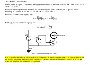
Transcribed Image Text:JFET Output Characteristics
For the circuit in Figure 13, determine the output characteristics of the JFET for VGS = -6V. AO1=-6V. IDSS=
110mA, Vp -8V.
Using the current equations for the linear and saturation regions, plot VDs (X-axis) vs. ID (y-axis) for the
following AO0 values: 0, 0.2, 0.6, 1.0, 1.4, 1.6, 2.0, 2.5, 3.0, 4.0 5.0 V.
For VDS (VGS-Vp) (linear region), use:
For VDS (VGS-VP) (saturation region), use:
Vp
ID
2/pss (VGS -VP-VDS) VDS
2
ID =
= loss (1 - Vas) ²
Vp
AOO
GND
AO1
J1
Ammeter
Figure 13: JFET Output Characteristics Circuit
Hint: Assuming a negligible voltage drop over the ammeter, it is safe to assume A00=VDs. Also, recognize that
the saturation equation does not contain a VDs term. Take care not to drop the negative sign off of VGs or VP
when you substitute the values into the equations.
Expert Solution
This question has been solved!
Explore an expertly crafted, step-by-step solution for a thorough understanding of key concepts.
Step by stepSolved in 2 steps with 5 images

Knowledge Booster
Similar questions
- Set up a midpoint bias for a JFET with IDSS = 14 mA and VGS(off) = -10 V. Use a 24 V dc source as the supply voltage. Show the circuit and resistor values. Indicate the value of ID. Indicate the value of VGS. Indicate the value of VDS.arrow_forward24. Set up a midpoint bias for a JFET with Ipss = 14 mA and VGs(ofm = -10 V. Use a 24 V dc source as the supply voltage. Show the circuit and resistor values. Indicate the values of Ip, VGs, and Vps-arrow_forwardDetermine VB, VE, VC, VCE, IB, IE, and IC in Figure. The 2N3904 is a general purpose transistor with a typical BDC 200 Vcc +30 V WWII VCE VB R₁ • 22 ΚΩ IC(mA) Chọn... * Chọn... * IB(UA) Chọn... * IE(MA) Chọn... ◆ Chọn... * Chọn... * Chọn... * VE VC R₂ ´ 10 ΚΩ www Rc 1.0 ΚΩ 2N3904 PDC=200 RE 1.0 ΚΩarrow_forward
- The circuit shown in the following in figure has: VIN= 10 V, Vz = 7.2 V@ Iz-40 mA, Izk =2 mA, IzM= 100 mA and Zz-5 2. Determine a) Maximum output voltage. b) Minimum output voltage. c) The percentage load regulation. d) The minimum permissible load resistor value. c) The maximum permissible load resistor value. R 2211 VISarrow_forward0please see both images to solvearrow_forward4. Line Regulation is determined by: a. Load current b. Changes in the load resistance and output voltage C. Changes in output and input voltage below detaarrow_forward
- What is the differential gain of the differnce stage of the instrumentation apmplifier? What is the overall differnential gain of the instrumentation apmplifier?arrow_forwardThe controlling parameter in MOSFET is a) Vds b) lg c) Vgs d) Isarrow_forwardProblem5: For the common base circurt shown in figure find I. and VCB. Assume transistor is Silicon (a-0.98) Ic Rp= 1.5 ko Rc= 1.2 kn VEE = 8 V. Vcc= 18 Varrow_forward
- Consider the circuit in Figure A4. (a) Explain its operation with the aid of diagrams. (b) Assume that R₁ = 21 kQ, Vref = 1.2 V, Vs = +12 V and -Vs = -12 V. Determine a value for R₂ to obtain a maximum threshold voltage of Vth = 5.25 V. (c) Sketch the output voltage signal in time for a sinusoidal input signal of peak voltage 3.5 V and frequency 2 kHz. R1 R2 Vout Vref Vin +Vs -Vs Figure A4arrow_forwardplease show step by step working for this question with circuit diagrams if possible so I can understand the circuit better thank you.(please handwrite the solutions)arrow_forwardDesign a voltage regulator circuit to supply a constant voltage of (10 V) across a resistive load of (10 ). The minimum Zener current is (50 mA) and maximum current is (800 mA). AssumeRs=10 andFind:- 1- the maximum and minimum source voltage. 2- at the maximum source voltage, find the minimum load resistance. 3- at the minimum source voltage, find the maximum load resistance. 4- minimum and maximum power dissipated in the Zener diode.arrow_forward
arrow_back_ios
SEE MORE QUESTIONS
arrow_forward_ios
Recommended textbooks for you
 Introductory Circuit Analysis (13th Edition)Electrical EngineeringISBN:9780133923605Author:Robert L. BoylestadPublisher:PEARSON
 Delmar's Standard Textbook Of ElectricityElectrical EngineeringISBN:9781337900348Author:Stephen L. HermanPublisher:Cengage Learning
 Programmable Logic ControllersElectrical EngineeringISBN:9780073373843Author:Frank D. PetruzellaPublisher:McGraw-Hill Education
 Fundamentals of Electric CircuitsElectrical EngineeringISBN:9780078028229Author:Charles K Alexander, Matthew SadikuPublisher:McGraw-Hill Education
 Electric Circuits. (11th Edition)Electrical EngineeringISBN:9780134746968Author:James W. Nilsson, Susan RiedelPublisher:PEARSON
 Engineering ElectromagneticsElectrical EngineeringISBN:9780078028151Author:Hayt, William H. (william Hart), Jr, BUCK, John A.Publisher:Mcgraw-hill Education,

Introductory Circuit Analysis (13th Edition)
Electrical Engineering
ISBN:9780133923605
Author:Robert L. Boylestad
Publisher:PEARSON

Delmar's Standard Textbook Of Electricity
Electrical Engineering
ISBN:9781337900348
Author:Stephen L. Herman
Publisher:Cengage Learning

Programmable Logic Controllers
Electrical Engineering
ISBN:9780073373843
Author:Frank D. Petruzella
Publisher:McGraw-Hill Education

Fundamentals of Electric Circuits
Electrical Engineering
ISBN:9780078028229
Author:Charles K Alexander, Matthew Sadiku
Publisher:McGraw-Hill Education

Electric Circuits. (11th Edition)
Electrical Engineering
ISBN:9780134746968
Author:James W. Nilsson, Susan Riedel
Publisher:PEARSON

Engineering Electromagnetics
Electrical Engineering
ISBN:9780078028151
Author:Hayt, William H. (william Hart), Jr, BUCK, John A.
Publisher:Mcgraw-hill Education,