Introductory Circuit Analysis (13th Edition)
13th Edition
ISBN: 9780133923605
Author: Robert L. Boylestad
Publisher: PEARSON
expand_more
expand_more
format_list_bulleted
Question

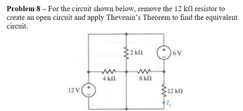
Transcribed Image Text:Problem 8 - For the circuit shown below, remove the 12 k resistor to
create an open circuit and apply Thevenin's Theorem to find the equivalent
circuit.
2 ΚΩ
6V
ww
ww
4 ΚΩ
8 ΚΩ
12 V
12 ΚΩ
1
Expert Solution
This question has been solved!
Explore an expertly crafted, step-by-step solution for a thorough understanding of key concepts.
Step by stepSolved in 2 steps with 3 images

Knowledge Booster
Similar questions
- Initially a 10 V battery is in series with a 100 ohm resistor and a 2 mH inductor. After along time, a switch is thrown to remove the battery from the circuit, and replacing itwith another 100 ohm resistor (and so the inductor ends up with two 100 ohm resistorsin series).What is the current at t=0 s (immediately after the switch is thrown)?What is the current at t=5 s later?arrow_forwardThe parallel combination of R2 and C2 in the circuit shown represents the input circuit to a cathode-ray oscilloscope (CRO). The parallel combination of R1 and C1 is a circuit model of a compensating lead that is used to connect the CRO to the source. There is no energy stored in C1 or C2 at the time when the 10 V source is connected to the CRO via the compensating lead. The circuit values are C1=4 pF, C2=16 pF, R1=1.25 MΩ, and R2=5 MΩ. 1. a) Find vo. 2. b) Find io. 3. c) Repeat (a) and (b) given C1 is changed to 64 pF.arrow_forwardFind R1, R2, and L in this circuitarrow_forward
- Hello, I am very confused what is a hyrbrid pi model. Can you please make a hypbrid pi model from this circuit and explain thank you I will likearrow_forwardPlease can you help me solve this step by steparrow_forwardThe image contains the problems that need to be solved. This is a voltage divider circuit, and it is understood that V0 is maximized when one of the resistors is at its maximum value while the other is at its minimum (and vice versa for the minimum V0). The answers are provided, but the process is needed.arrow_forward
- A battery is comprised of 4 cells connected in parallel, each cell has an EMF with 1.5V and an internal resistance of 600.00 mΩ. There is no load connected to the terminal. Solve for Rint.arrow_forwardNeed help ON (iii)...Please help with step by step explainationarrow_forwardAnyone familiar with this to provide step by step explanation? TIAarrow_forward
arrow_back_ios
SEE MORE QUESTIONS
arrow_forward_ios
Recommended textbooks for you
 Introductory Circuit Analysis (13th Edition)Electrical EngineeringISBN:9780133923605Author:Robert L. BoylestadPublisher:PEARSON
 Delmar's Standard Textbook Of ElectricityElectrical EngineeringISBN:9781337900348Author:Stephen L. HermanPublisher:Cengage Learning
 Programmable Logic ControllersElectrical EngineeringISBN:9780073373843Author:Frank D. PetruzellaPublisher:McGraw-Hill Education
 Fundamentals of Electric CircuitsElectrical EngineeringISBN:9780078028229Author:Charles K Alexander, Matthew SadikuPublisher:McGraw-Hill Education
 Electric Circuits. (11th Edition)Electrical EngineeringISBN:9780134746968Author:James W. Nilsson, Susan RiedelPublisher:PEARSON
 Engineering ElectromagneticsElectrical EngineeringISBN:9780078028151Author:Hayt, William H. (william Hart), Jr, BUCK, John A.Publisher:Mcgraw-hill Education,

Introductory Circuit Analysis (13th Edition)
Electrical Engineering
ISBN:9780133923605
Author:Robert L. Boylestad
Publisher:PEARSON

Delmar's Standard Textbook Of Electricity
Electrical Engineering
ISBN:9781337900348
Author:Stephen L. Herman
Publisher:Cengage Learning

Programmable Logic Controllers
Electrical Engineering
ISBN:9780073373843
Author:Frank D. Petruzella
Publisher:McGraw-Hill Education

Fundamentals of Electric Circuits
Electrical Engineering
ISBN:9780078028229
Author:Charles K Alexander, Matthew Sadiku
Publisher:McGraw-Hill Education

Electric Circuits. (11th Edition)
Electrical Engineering
ISBN:9780134746968
Author:James W. Nilsson, Susan Riedel
Publisher:PEARSON

Engineering Electromagnetics
Electrical Engineering
ISBN:9780078028151
Author:Hayt, William H. (william Hart), Jr, BUCK, John A.
Publisher:Mcgraw-hill Education,