
Principles of Geotechnical Engineering (MindTap Course List)
9th Edition
ISBN: 9781305970939
Author: Braja M. Das, Khaled Sobhan
Publisher: Cengage Learning
expand_more
expand_more
format_list_bulleted
Related questions
Question
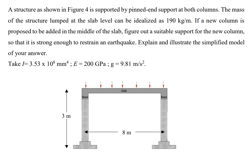

Transcribed Image Text:A structure as shown in Figure 4 is supported by pinned-end support at both columns. The mass
of the structure lumped at the slab level can be idealized as 190 kg/m. If a new column is
proposed to be added in the middle of the slab, figure out a suitable support for the new column,
so that it is strong enough to restrain an earthquake. Explain and illustrate the simplified model
of your answer.
Take I= 3.53 x 108 mmª ; E = 200 GPa ; g = 9.81 m/s².
3 m
Beam
Slab
8 m
Beam
Expert Solution
This question has been solved!
Explore an expertly crafted, step-by-step solution for a thorough understanding of key concepts.

Step by stepSolved in 4 steps with 8 images

Knowledge Booster


Learn more about
Need a deep-dive on the concept behind this application? Look no further. Learn more about this topic, civil-engineering and related others by exploring similar questions and additional content below.Similar questions
- Two line loads q1 and q2 of infinite lengths are acting on top of an elastic medium, as shown in Figure P8.6. Find the vertical stress increase at A.arrow_forwardEB and FG are two planes inside a soil element ABCD as shown in Figure 10.50. Stress conditions on the two planes are Plane EB: EB = 25 kN/m2; EB = +10 kN/m2 Plane FG: FG = 10 kN/m2; FG = 5 kN/m2 (Note: Mohrs circle sign conventions for stresses are used above) Given ; = 25, determine: a. The maximum and minimum principal stresses b. The angle between the planes EB and FG c. The external stresses on planes AB and BC that would cause the above internal stresses on planes EB and FGarrow_forwardA 9 ft wide and infinitely long flexible strip load of 800 lb/ft2 is placed on an elastic medium as shown in Figure P8.7. Find the vertical stress increase at points A, B, and C located 3 ft below the surface.arrow_forward
- Refer to Figure 8.24. Determine the vertical stress increase, , at point A with the following values: q1 = 100 kN/m x1 = 3 m z = 2 m q2 = 200 kN/m x2 = 2 m FIG. 8.24 Stress at a point due to two line loadsarrow_forwardThe soil profile at a site is shown Figure P16.3. Find the total horizontal normal stresses at A and B, assuming at-rest conditions.arrow_forwardRepeat Problem 10.12 for q = 700 kN/m2, B = 8 m, and z = 4 m. In this case, point A is located below the centerline under the strip load. 10.12 Refer to Figure 10.43. A strip load of q = 1450 lb/ft2 is applied over a width with B = 48 ft. Determine the increase in vertical stress at point A located z = 21 ft below the surface. Given x = 28.8 ft. Figure 10.43arrow_forward
- Use Eq. (6.14) to determine the stress increase () at z = 10 ft below the center of the area described in Problem 6.5. 6.5 Refer to Figure 6.6, which shows a flexible rectangular area. Given: B1 = 4 ft, B2 = 6 ft, L1, = 8 ft, and L2 = 10 ft. If the area is subjected to a uniform load of 3000 lb/ft2, determine the stress increase at a depth of 10 ft located immediately below point O. Figure 6.6 Stress below any point of a loaded flexible rectangular areaarrow_forwardRefer to Figure 10.42. Due to application of line loads q1 and q2, the vertical stress increase at point A is 58 kN/m2. Determine the magnitude of q2. Figure 10.42arrow_forwardSolve Problem 7.8 using Eq. (7.29). Ignore the post-construction settlement. 7.8 Solve Problem 7.4 with Eq. (7.20). Ignore the correction factor for creep. For the unit weight of soil, use γ = 115 lb/ft3. 7.4 Figure 7.3 shows a foundation of 10 ft × 6.25 ft resting on a sand deposit. The net load per unit area at the level of the foundation, qo, is 3000 lb/ft2. For the sand, μs = 0.3, Es = 3200 lb/in.2, Df = 2.5 ft, and H = 32 ft. Assume that the foundation is rigid and determine the elastic settlement the foundation would undergo. Use Eqs. (7.4) and (7.12).arrow_forward
- For the same line loads given in Problem 10.8, determine the vertical stress increase, z, at a point located 4 m below the line load, q2. Refer to Figure 10.41. Determine the vertical stress increase, z, at point A with the following values: q1 = 110 kN/m, q2 = 440 kN/m, x1 = 6 m, x2 = 3 m, and z = 4 m. Figure 10.41arrow_forwardConsider a continuous foundation of width B = 1.4 m on a sand deposit with c = 0, = 38, and = 17.5 kN/m3. The foundation is subjected to an eccentrically inclined load (see Figure 6.33). Given: load eccentricity e = 0.15 m, Df = 1 m, and load inclination = 18. Estimate the failure load Qu(ei) per unit length of the foundation a. for a partially compensated type of loading [Eq. (6.89)] b. for a reinforced type of loading [Eq. (6.90)]arrow_forwardA soil element beneath a pave ment experiences principal stress rotations when the wheel load, W, passes over it and moves away, as shown in Figure 10.51. In this case, the wheel load has passed over points A and B and is now over point C. The general state of stress at these points is similar to the one shown by a stress block at point D. The phenomenon of principal stress rotation influences the permanent deformation behavior of the pavement layers. Investigate how the magnitude and the orientations of the principal stresses vary with distance from the point of application of the wheel load. Consider the case shown in Figure 10.51. An unpaved aggregate road with a thickness of 610 mm and unit weight of 19.4 kN/m3 is placed over a soil subgrade. A typical single-axle wheel load, W = 40 kN, is applied uniformly over a circular contact area with a radius of R = 150 mm (tire pressure of 565 kN/m2). The horizontal and shear stresses at each point are calculated from a linear elastic finite element analysis for a two-layer pavement and are presented in the following table. a. Use Eq. (10.28) to calculate the vertical stress increases at soil elements A, B, and C that are located at radial distances 0.457,0.267, and 0 m, respectively, from the center of the load. Determine the total vertical stress (y) due to wheel load, the overburden pressure at each point, and enter these values in the table. b. Use the pole method to determine the maximum and minimum principal stresses (1 and 3) for elements A, B, and C. Also determine the orientation (s) of the principal stress with respect to the vertical. Enter these values in the table. c. Plot the variations of 1 and s, with normalized radial distance, r/R, from the center of loading.arrow_forward
arrow_back_ios
SEE MORE QUESTIONS
arrow_forward_ios
Recommended textbooks for you
- Principles of Geotechnical Engineering (MindTap C...Civil EngineeringISBN:9781305970939Author:Braja M. Das, Khaled SobhanPublisher:Cengage Learning
 Principles of Foundation Engineering (MindTap Cou...Civil EngineeringISBN:9781337705028Author:Braja M. Das, Nagaratnam SivakuganPublisher:Cengage Learning
 Principles of Foundation Engineering (MindTap Cou...Civil EngineeringISBN:9781305081550Author:Braja M. DasPublisher:Cengage Learning
  Fundamentals of Geotechnical Engineering (MindTap...Civil EngineeringISBN:9781305635180Author:Braja M. Das, Nagaratnam SivakuganPublisher:Cengage Learning
Principles of Geotechnical Engineering (MindTap C...
Civil Engineering
ISBN:9781305970939
Author:Braja M. Das, Khaled Sobhan
Publisher:Cengage Learning
Principles of Foundation Engineering (MindTap Cou...
Civil Engineering
ISBN:9781337705028
Author:Braja M. Das, Nagaratnam Sivakugan
Publisher:Cengage Learning
Principles of Foundation Engineering (MindTap Cou...
Civil Engineering
ISBN:9781305081550
Author:Braja M. Das
Publisher:Cengage Learning
Fundamentals of Geotechnical Engineering (MindTap...
Civil Engineering
ISBN:9781305635180
Author:Braja M. Das, Nagaratnam Sivakugan
Publisher:Cengage Learning