
Applied Statics and Strength of Materials (6th Edition)
6th Edition
ISBN: 9780133840544
Author: George F. Limbrunner, Craig D'Allaird, Leonard Spiegel
Publisher: PEARSON
expand_more
expand_more
format_list_bulleted
Videos
Textbook Question
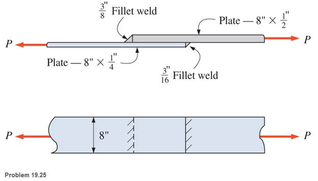
Chapter 19, Problem 19.25SP
Determine the allowable tensile load that can be applied to the connection shown. The plates are of ASTM A36 steel and the weld is made u sing an E70 electrode.
Expert Solution & Answer
Want to see the full answer?
Check out a sample textbook solution
Students have asked these similar questions
8. Design the length of weld (L) in the connection below to develop the full
tensile capacity of the plate. Use E70 electrodes and 1/4" side fillet welds. The
material is ASTM A36 Steel and the allowable axial tensile stress is 22,000 psi.
(show all your work)
"L"
PL 1/2"
PL 3/8" x 6"
P
Situation 2: The lap splice shown will develop a full strength as shown in the figure. Using E70 electrodes.
The width of the plate is 150 mm and the thickness is 10 mm. Use Fy = 248 MPa
T4
46 mm
48 mm
1. Which of the following nearly gives the diameter of the slot weld using the LRFD method.
O 45 mm
T
O 47 mm
T
W
An angle iron made of AISI 1040 CD steel is welded to metal as shown and loaded with a dynamic load varying between +40kN and +60kN. E70XX (Sut = 482MPa, Sy = 393MPa) will be used as the welding electrode. Find the factor of safety of the weld zone. Note: that both static and dynamic loads are applied to the source.
Chapter 19 Solutions
Applied Statics and Strength of Materials (6th Edition)
Ch. 19 - Prob. 19.1PCh. 19 - Rework Problem 19.1 assuming a bearing-type...Ch. 19 - Rework Problem 19.1 assuming a bearing-type...Ch. 19 - Compute the allowable tensile load for the...Ch. 19 - Rework Problem 19.4 assuming a bearing-type...Ch. 19 - Rework Problem 19.4 assuming that the bolts are 34...Ch. 19 - Select the number and arrangement of 34 in....Ch. 19 - Calculate the allowable tensile load for the...Ch. 19 - In the connection shown, 14 in. side and end...Ch. 19 - Design the fillet welds parallel to the applied...
Ch. 19 - A fillet weld between two steel plates...Ch. 19 - Design an end connection using longitudinal welds...Ch. 19 - Calculate the allowable tensile load for the butt...Ch. 19 - Calculate the allowable tensile load for the lap...Ch. 19 - Calculate the allowable tensile load for the butt...Ch. 19 - Rework Problem 19.10 assuming that both plates are...Ch. 19 - Rework Problem 19.12 assuming that the angle is an...Ch. 19 - Two ASTM A36 steel plates, each 12 in. by 12 in. ,...Ch. 19 - Rework Problem 19.20 changing the fasteners to 34...Ch. 19 - Calculate the minimum main plate thickness for the...Ch. 19 - A roof truss tension member is made up of 2L6412...Ch. 19 - Rework Problem 19.23 changing the fasteners to six...Ch. 19 - Determine the allowable tensile load that can be...Ch. 19 - The welded connection shown is subjected to an...Ch. 19 - In Problem 19.26, use a 38 in. fillet weld, change...
Knowledge Booster


Learn more about
Need a deep-dive on the concept behind this application? Look no further. Learn more about this topic, mechanical-engineering and related others by exploring similar questions and additional content below.Similar questions
- 3.) The diagram below shows a 5.5m long double angle brace which is connected by 6mm welding connection. The length of weld shown in the picture is 300 mm on the top and 100 mm on the bottom. The 2-L127x 89x6.4 are 300W steel and long leg back-to-back. The braces are to be welded to a 12 mm 350W steel gusset plate. Determine the factored tensile capacity of the angles. Any intermediate connections that are required should also be specified. 740 kN -12 mm Gusset Platearrow_forwardQ1: The weldment shown in the figure is subjected to a force F. The hot-rolled steel bar has a thickness and is of AISI 1040 steel. The vertical support is likewise AISI 1040 HR steel. The electrode is given in the table below. Estimate the static load F the bar can carry if two fillet welds are used. h (mm) b (mm) 30 d (mm) 70 Elecrode E8010arrow_forwardTe - Effective throat thickness well in mm = 6 sin45° Consider the following drawing in which plate 1 is welded onto plate 2 as shown for tensile and shear loading. The plates are fillet welded with a weld thickness of 6 mm as shown for a length of 150 mm. The plates have an ultimate strength of 275 MPa and the welding was done with F70 welding electrodes, which possesses an ultimate strength of 483 MPa. Consider a partial factor of safety of 1.7 for the welded joint and determine the design strength of the weld joint, both in tension (Tdw) and in shear (Vdw) due to the forces acting on it. a) Determine the design strength of the following weld in tension ( ) due to vertical forces. b) Determine the design strength of the weld in shear ( ) due to horizontal forces. Attached pic is shear equation for calculation Tension equation for calculation is: Tdw = FyLwte /Ymwarrow_forward
- Q1: The weldment shown in the figure is subjected to a force F. The hot-rolled steel bar has a thickness h and is of AISI 1040 steel. The vertical support is likewise AISI 1040 HR steel. The electrode is given in the table below. Estimate the static load F the bar can carry if two fillet welds are used. b (mm) d (mm) h (mm) Elecrode E8010 30 70 6 ko →→ Farrow_forwardQ1: The weldment shown in the figure is subjected to a force F. The hot-rolled steel bar has a thickness h and is of AISI 1040 steel. The vertical support is likewise AISI 1040 HR steel. The electrode is given in the table below. Estimate the static load F the bar can carry if two fillet welds are used. b (mm) h (mm) d (mm) 70 Elecrode E8010 30 6 b→→ Farrow_forwardQ1: The weldment shown in the figure is subjected to a force F. The hot-rolled steel bar has a thickness h and is of AISI 1040 steel. The vertical support is likewise AISI 1040 HR steel. The electrode is given in the table below. Estimate the static load F the bar can carry if two fillet welds are used. b (mm) h (mm) d (mm) 70 Elecrode E8010 30 4arrow_forward
- Q1: The weldment shown in the figure is subjected to a force F. The hot-rolled steel bar has a thickness h and is of AISI 1040 steel. The vertical support is likewise AISI 1040 HR steel. The electrode is given in the table below. Estimate the static load F the bar can carry if two fillet welds are used. b (mm) h (mm) d (mm) 70 Elecrode E8010 30 6 1-b- Farrow_forwardfind the tensile of the bolt with diameter 38mm,80kNarrow_forwardQ1: The weldment shown in the figure is subjected to a force F. The hot-rolled steel bar has a thickness h and is of AISI 1040 steel. The vertical support is likewise AISI 1040 HR steel. The electrode is given in the table below. Estimate the static load F the bar can carry if two fillet welds are used. d (mm) h (mm) Elecrode b (mm) 30 70 6 E8010 4 ko →arrow_forward
- 2. A G10200 HR steel bar of thickness h is welded to a vertical support of the same material as shown below. If an E6010 electrode is used, determine the maximum force F that can be applied while satisfying welding code. The dimensions are h=5 mm, b = 50 mm, and d = 50 mm. HINT: you will need to check failure of the weld material and base materials. d b h Farrow_forwardappropriate length of the weld joint shown in the figure if the force is equal to (60000lb) and the operating stress value is (60ksi) and the size of the weld is (1/4in).arrow_forwardTwo plates, 25 mm thick, are welded together by means of trans verse-fillet welds. The ultimate tensile strength of a weld metal is 415 MPa. The surface finish factor of the weld surface is 0.5, and the size factor is 0.85. The reliability is 90%. Determine the length of the weld if the factor of safety is 2. The transverse force on the welds is 100 kN, which is completely reversed under fatigue loading. Take: A=10mm 25 Toe Р.arrow_forward
arrow_back_ios
SEE MORE QUESTIONS
arrow_forward_ios
Recommended textbooks for you
 Elements Of ElectromagneticsMechanical EngineeringISBN:9780190698614Author:Sadiku, Matthew N. O.Publisher:Oxford University Press
 Mechanics of Materials (10th Edition)Mechanical EngineeringISBN:9780134319650Author:Russell C. HibbelerPublisher:PEARSON
 Thermodynamics: An Engineering ApproachMechanical EngineeringISBN:9781259822674Author:Yunus A. Cengel Dr., Michael A. BolesPublisher:McGraw-Hill Education
 Control Systems EngineeringMechanical EngineeringISBN:9781118170519Author:Norman S. NisePublisher:WILEY
 Mechanics of Materials (MindTap Course List)Mechanical EngineeringISBN:9781337093347Author:Barry J. Goodno, James M. GerePublisher:Cengage Learning
 Engineering Mechanics: StaticsMechanical EngineeringISBN:9781118807330Author:James L. Meriam, L. G. Kraige, J. N. BoltonPublisher:WILEY
Elements Of Electromagnetics
Mechanical Engineering
ISBN:9780190698614
Author:Sadiku, Matthew N. O.
Publisher:Oxford University Press
Mechanics of Materials (10th Edition)
Mechanical Engineering
ISBN:9780134319650
Author:Russell C. Hibbeler
Publisher:PEARSON
Thermodynamics: An Engineering Approach
Mechanical Engineering
ISBN:9781259822674
Author:Yunus A. Cengel Dr., Michael A. Boles
Publisher:McGraw-Hill Education
Control Systems Engineering
Mechanical Engineering
ISBN:9781118170519
Author:Norman S. Nise
Publisher:WILEY
Mechanics of Materials (MindTap Course List)
Mechanical Engineering
ISBN:9781337093347
Author:Barry J. Goodno, James M. Gere
Publisher:Cengage Learning
Engineering Mechanics: Statics
Mechanical Engineering
ISBN:9781118807330
Author:James L. Meriam, L. G. Kraige, J. N. Bolton
Publisher:WILEY
Differences between Temporary Joining and Permanent Joining.; Author: Academic Gain Tutorials;https://www.youtube.com/watch?v=PTr8QZhgXyg;License: Standard Youtube License