
Applied Statics and Strength of Materials (6th Edition)
6th Edition
ISBN: 9780133840544
Author: George F. Limbrunner, Craig D'Allaird, Leonard Spiegel
Publisher: PEARSON
expand_more
expand_more
format_list_bulleted
Concept explainers
Videos
Textbook Question
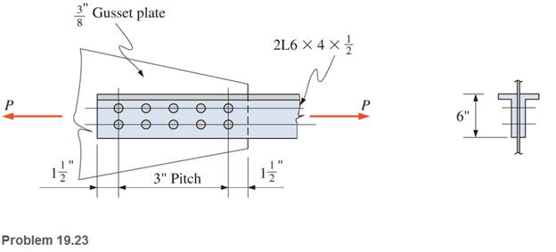
Chapter 19, Problem 19.23SP
A roof truss tension member is made up of
Expert Solution & Answer
Want to see the full answer?
Check out a sample textbook solution
Students have asked these similar questions
Two plates each with thickness of 18 mm are bolted together with 6 – 20mm ø bolts forming
a lap connection. Bolt spacing are as follows:
X1 = 50 mm,
X2 = 120 mm and
X3 = 100 mm
FvRivet = 130 MPa.
Calculate the the pemissible tensile load P under the following conditions.
a. Based on the effective net area.
b. Based on block shear.
c. Based on the safe value of P.
Find the Axial Forces in members 1 - 5.
Find the Displacement Displacement of joint A (mm, positive right and up) for both Horizontal and Vertical
A cylinder head for steam engine is held by (14) bolts. The effective diameter of the
cylinder is (350 mm) and the steam pressure is (0.85 MPa) .find the size of the bolt if
tensile stress is not to exceed (35 MPa)
Chapter 19 Solutions
Applied Statics and Strength of Materials (6th Edition)
Ch. 19 - Prob. 19.1PCh. 19 - Rework Problem 19.1 assuming a bearing-type...Ch. 19 - Rework Problem 19.1 assuming a bearing-type...Ch. 19 - Compute the allowable tensile load for the...Ch. 19 - Rework Problem 19.4 assuming a bearing-type...Ch. 19 - Rework Problem 19.4 assuming that the bolts are 34...Ch. 19 - Select the number and arrangement of 34 in....Ch. 19 - Calculate the allowable tensile load for the...Ch. 19 - In the connection shown, 14 in. side and end...Ch. 19 - Design the fillet welds parallel to the applied...
Ch. 19 - A fillet weld between two steel plates...Ch. 19 - Design an end connection using longitudinal welds...Ch. 19 - Calculate the allowable tensile load for the butt...Ch. 19 - Calculate the allowable tensile load for the lap...Ch. 19 - Calculate the allowable tensile load for the butt...Ch. 19 - Rework Problem 19.10 assuming that both plates are...Ch. 19 - Rework Problem 19.12 assuming that the angle is an...Ch. 19 - Two ASTM A36 steel plates, each 12 in. by 12 in. ,...Ch. 19 - Rework Problem 19.20 changing the fasteners to 34...Ch. 19 - Calculate the minimum main plate thickness for the...Ch. 19 - A roof truss tension member is made up of 2L6412...Ch. 19 - Rework Problem 19.23 changing the fasteners to six...Ch. 19 - Determine the allowable tensile load that can be...Ch. 19 - The welded connection shown is subjected to an...Ch. 19 - In Problem 19.26, use a 38 in. fillet weld, change...
Knowledge Booster


Learn more about
Need a deep-dive on the concept behind this application? Look no further. Learn more about this topic, mechanical-engineering and related others by exploring similar questions and additional content below.Similar questions
- (1) E 4 kips C Lon -9 ft-9 ft——9 ft——94—- 1 kips What are the member forces in BD, BE and CE? Indicate if they are in tension (T) or compression (C).arrow_forward3- Select an unequal -leg angle tension member 15 feet long to resist a service dead load of 35 kips and a service live load of 70 kips. Use A36 steel. The connection is shown in figure. 3/4 in-diameter boltsarrow_forward300 N - 0,3 m 0.4 m For the shown figure, sketch the free body diagram for each element. The links section is a square of 0.2 ni 30x30 mm. The link material is ST37 with yield stress of 210Mpa and modulus of elasticity is 210000 MPa. For link BEC, calculate all the stresses and the compound stress at 0.7 m the critical section. Check the links DE for buckling.arrow_forward
- 2. A 2-in.-diameter steel tube with a wall thickness of 0.05 inch just fits in a rigid hole. Find the tangential stress if an axial compressive load of 3140 lb is applied. Assume v=0.30 and neglect the possibility of buckling. data: 2 in Rod Wall Rod Villarrow_forwardThe figure gives the cross-section of a grade 25 cast-iron pressure vessel. A total of N bolts are to be used to resist a separating force of 150 kN. (a) Determine kb, km, and C. (b) Find the number of bolts required for a load factor of 2 where the bolts may be reused when the joint is taken apart. (c) With the number of bolts obtained in part (b), determine the realized load factor for overload, the yielding factor of safety, and the load factor for joint separation. Use (SI) units as it appliesarrow_forwardThe figures below show a formed sheet-steel bracket. The total distributed load “W” on the bracket is 20 kN. It is secured to the support with two grade 5.8 bolts. The joint constant is C=0.183, and the bolts are preloaded to 70 percent of the proof load. The dimensions of the top flange are the same as the mounting flange.a) Find the external loads (P1 and P2) carried by upper and bottom bolts respectively if both resist the moment?b) Find the upper bolt diameter by ignoring direct shear load and determine/select a standard metric bolt size with a pitch for a design factor of 1,4.c) Is there any need to enlarge 5 mm dia. holes in the bracket?arrow_forward
- Question 4 of 10 -/ 10 Current Attempt in Progress AWT205 x 30 structural steel section (see Appendix B for cross-sectional properties) is used for a 6.6 mcolumn. Assume pinned connections at each end of the column. Determine: (a) the slenderness ratio. (bi the Euler buckling load. Use E- 200 GPa for the steel. (c) the asdal stress in the columnwhen the Euler load is applied. Part 1 Use Appendix B to lookup the cross-sectional area, the area moment of inertia, and the radius of gyration for a WT205 x 30 structural steel section. Answer A x 10 mm mm x 10 mm mmarrow_forwardTwo plates of which (2.5 d) and d as outer and inner diameter respectively and thickness 25 mm each are held together by means of a bolt. The bolt material S-400 N/mm² and E210000 N/mm² while plate material E= 72000 N/mm². The initial preload in the bold is 6.0 KN and force on the joint is 12 kN. Find out size of bolt assuming factor of safety 2.0.arrow_forwardFor the joint shown below, an SAE Grade 5 7/8-9 screw connects two plates. The joint stiffness constant (C) has already been calculated to be 0.2012. The pre-load (F;) in the screw is 34500 lb. If an external axial load (P) of 6300 lb is applied to the connection, what is the magnitude of the (compressive) load in the material (in units of kip)? P P red 29.4673 (with margin: 0.5893) wersarrow_forward
- a. Two brass rods used as compression members, each of 3-m effective length with pin end, have the cross sections shown in Figure Q5a. Determine the wall thickness of the hollow square rod for which the rods have the same critical buckling load. UZA O 40 mm 60 mm Figure Q5a 60 mm MALAYSIA UTM ERSITI TEKNO UNIVERSITI TEKNOLL 01arrow_forwardA bar of length 5 m is subjected to an axial tensile out of 100 KN The bar is 25 min diameter for 2 mof its length 30 mm diameter for I mor its length, and 20 mm diameter for the remaining 2 m of its length, Taking E= 2 x 10' Calculate the total increase in length of the bur.arrow_forward15 in 24 in The machine link shown is subjected to an axial load P, as shown. The link is pinned-pinned for buckling about the x-axis. The link is fixed-fixed for buckling about the y-axis. Assume the link is made of aluminum (E = 10000 ksi) and has a rectangular cross- %3D section. Which axis will buckle first? Ox-axis y-axis Both will buckle at the same force Not enough informationarrow_forward
arrow_back_ios
SEE MORE QUESTIONS
arrow_forward_ios
Recommended textbooks for you
 Elements Of ElectromagneticsMechanical EngineeringISBN:9780190698614Author:Sadiku, Matthew N. O.Publisher:Oxford University Press
 Mechanics of Materials (10th Edition)Mechanical EngineeringISBN:9780134319650Author:Russell C. HibbelerPublisher:PEARSON
 Thermodynamics: An Engineering ApproachMechanical EngineeringISBN:9781259822674Author:Yunus A. Cengel Dr., Michael A. BolesPublisher:McGraw-Hill Education
 Control Systems EngineeringMechanical EngineeringISBN:9781118170519Author:Norman S. NisePublisher:WILEY
 Mechanics of Materials (MindTap Course List)Mechanical EngineeringISBN:9781337093347Author:Barry J. Goodno, James M. GerePublisher:Cengage Learning
 Engineering Mechanics: StaticsMechanical EngineeringISBN:9781118807330Author:James L. Meriam, L. G. Kraige, J. N. BoltonPublisher:WILEY
Elements Of Electromagnetics
Mechanical Engineering
ISBN:9780190698614
Author:Sadiku, Matthew N. O.
Publisher:Oxford University Press
Mechanics of Materials (10th Edition)
Mechanical Engineering
ISBN:9780134319650
Author:Russell C. Hibbeler
Publisher:PEARSON
Thermodynamics: An Engineering Approach
Mechanical Engineering
ISBN:9781259822674
Author:Yunus A. Cengel Dr., Michael A. Boles
Publisher:McGraw-Hill Education
Control Systems Engineering
Mechanical Engineering
ISBN:9781118170519
Author:Norman S. Nise
Publisher:WILEY
Mechanics of Materials (MindTap Course List)
Mechanical Engineering
ISBN:9781337093347
Author:Barry J. Goodno, James M. Gere
Publisher:Cengage Learning
Engineering Mechanics: Statics
Mechanical Engineering
ISBN:9781118807330
Author:James L. Meriam, L. G. Kraige, J. N. Bolton
Publisher:WILEY
Types Of loads - Engineering Mechanics | Abhishek Explained; Author: Prime Course;https://www.youtube.com/watch?v=4JVoL9wb5yM;License: Standard YouTube License, CC-BY