
Applied Statics and Strength of Materials (6th Edition)
6th Edition
ISBN: 9780133840544
Author: George F. Limbrunner, Craig D'Allaird, Leonard Spiegel
Publisher: PEARSON
expand_more
expand_more
format_list_bulleted
Videos
Textbook Question
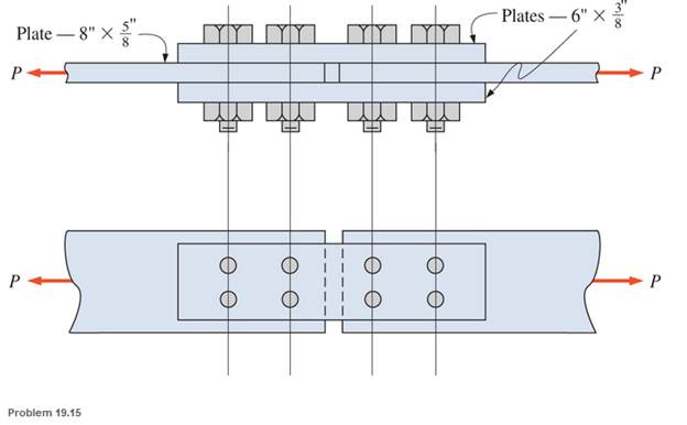
Chapter 19, Problem 19.15SP
Calculate the allowable tensile load for the butt joint shown. The fasteners are
Expert Solution & Answer
Want to see the full answer?
Check out a sample textbook solution
Students have asked these similar questions
Use LRFD and design a 13-foot-long tension member and its connection for a service dead load of 8 kips and a service live load of 24 kips. No slip of the connection is permitted. The connection will be to a 3⁄8-inch-thick gusset plate, as shown in Figure . Use a single angle for the tension member. Use Group A bolts and A572 Grade 50 steel for both the tension member and the gusset plate.
Design a cotter joint to support a axial load of122kN
kN . Carbon steel material selected which
has Tensile stress = 100MPa Compressive stress =150MPa; Shear stress=60MPa
As shown in figure below, two plates are clamped by washer-faced 2 in-20 UNF SAE
grade 5 bolts each with a standard 2 N steel plain washer.
The top plate is steel and the bottom pplate is gray cast
iron. If a total of 8 bolts where used to close 1 feet
diameter pipe which applied at maximum pressure of
150 psi. Calculate the static and fatigue safety factor of
this joint. Used Goodman theory for tha fatigue safety
1/2
factor.
3/4
Chapter 19 Solutions
Applied Statics and Strength of Materials (6th Edition)
Ch. 19 - Prob. 19.1PCh. 19 - Rework Problem 19.1 assuming a bearing-type...Ch. 19 - Rework Problem 19.1 assuming a bearing-type...Ch. 19 - Compute the allowable tensile load for the...Ch. 19 - Rework Problem 19.4 assuming a bearing-type...Ch. 19 - Rework Problem 19.4 assuming that the bolts are 34...Ch. 19 - Select the number and arrangement of 34 in....Ch. 19 - Calculate the allowable tensile load for the...Ch. 19 - In the connection shown, 14 in. side and end...Ch. 19 - Design the fillet welds parallel to the applied...
Ch. 19 - A fillet weld between two steel plates...Ch. 19 - Design an end connection using longitudinal welds...Ch. 19 - Calculate the allowable tensile load for the butt...Ch. 19 - Calculate the allowable tensile load for the lap...Ch. 19 - Calculate the allowable tensile load for the butt...Ch. 19 - Rework Problem 19.10 assuming that both plates are...Ch. 19 - Rework Problem 19.12 assuming that the angle is an...Ch. 19 - Two ASTM A36 steel plates, each 12 in. by 12 in. ,...Ch. 19 - Rework Problem 19.20 changing the fasteners to 34...Ch. 19 - Calculate the minimum main plate thickness for the...Ch. 19 - A roof truss tension member is made up of 2L6412...Ch. 19 - Rework Problem 19.23 changing the fasteners to six...Ch. 19 - Determine the allowable tensile load that can be...Ch. 19 - The welded connection shown is subjected to an...Ch. 19 - In Problem 19.26, use a 38 in. fillet weld, change...
Knowledge Booster


Learn more about
Need a deep-dive on the concept behind this application? Look no further. Learn more about this topic, mechanical-engineering and related others by exploring similar questions and additional content below.Similar questions
- Which of the following is the permissible working stress in psi of UNC bolts that has a stress area of 0.4 sq. in if material used is carbon steel with C = 5000?arrow_forward3. An M16 x 2 bolt with a slotted hex nut is used to clamp together two 25 mm steel plates. The joint is assembled with a size 16 N washer underneath the bolt head. The bolt is a 5.8 class metric grade, with a proof strength of 380 MPa. The joint is intended to be permanent. Determine a suitable length for the bolt, rounded up to the nearest standard size in millimeters. Calculate the bolt stiffness, the elongation of the bolt after the necessary preload is developed, and the bolt torque required to apply the preload. Assume that coefficients of friction between the bolt, nut, and collar are all ~0.15. For steel, use E = 207 GPa. Standard threaded fastener lengths, dimensions of hexagonal nuts, and dimensions of metric plain washers are provided in the textbook appendices.arrow_forwardTwo steel plates, with identical thickness of 15 mm, are joined by a 10-mm bolt and nut (no washers). The bolt is of ISO class 9.8. The joint is to be reusable. The joint stiffness constant is 0.11. The external load fluctuates between 0 and P(Newtons). In which failure mode the joint is most likely to fail if the value of P is increased continuously?arrow_forward
- Investigate the helical compression springs with squared and ground ends fabricated from A313 stainless steel to see if they are solid safe. If not, what is the largest free length to which they can be wound using ng = 1.2? Given: d= 0.0508 in, OD = 0.249 in, Nt = 11.2 coils, and Lo= 0.72 in. NOTE: This is a multi-part question. Once an answer is submitted, you will be unable to return to this part. Determine the values of the solid height, Ls, the spring rate, k, and the shear stress. The solid height, Ls, is .569 in. The spring rate, k, is Ibf/in. The shear stress is kpsi.arrow_forward200 mm 300 mm 42818 N B = 60° A lifting lug is to be mounted. The lug is shown on the drawing and the force is expected on the lug. The lug has a thickness of 30 mm. Calculate the minimum size of the weld for the given load case to ensure a minimum FOS of 3. Assume an AWS number E70xx electrode is used.arrow_forwardA 30-mm thick AISI 1020 steel plate is sandwiched between two 20-mm thick2024-T3 aluminum plates and compressed with a bolt and nut with no washers. The boltis M12 × 1.75, property class 9.8. Draw a sketch of the joint and,(a) Determine a suitable length for the bolt, rounded up to the nearest 5 mm. (b) Determine the bolt stiffness.(c) Determine the stiffness of the members and joint stiffness.arrow_forward
- A cylindrical pressure vessel, mean radius 15 in, is filled with a gas of molecular weight causing an internal pressure of 3500 psi. The efficiency of welded connection in the vessel is 78%. Assuming the material of the vessel to have a yield strength of 12 x 10⁴ psi, calculate for this strength the thickness of the vessel assuming a factor of safety of 1.5. draw diagramarrow_forwardA cantilever is to be attached to the flat side of a 6-in wide channel used as a column. The cantilever is to carry a load as shown in the figure. If two fasteners are used, should the array be arranged vertically, horizontally, or diagonally? How would you decide? Specify an optimal bolt pattern and size the bolts. 6 in- 6 in 6 in -in steel plate + 2000 lbfarrow_forwardPre-tensioning of a bolted joint is used to (a) strain harden the bolt head (b) decrease stiffness of the bolted joint (c) increase stiffness of the bolted joint (d) prevent yielding of the thread rootarrow_forward
- Determine the safe tensile load for bolts of (a)M 17and (b) M 26. Assume that the bolts are not initially stressed and take the safe tensile stress as 305MPa.arrow_forwardFor the joint shown below, a Metric grade 8.8 M90x6 screw connects two plates. The joint stiffness constant (C) has already been calculated to be 0.3442. The pre-load (F;) in the screw is 2045.9 kN. If an external axial load, varying from -16.4 kN to 954.4 kN, is applied to the connection, what is the factor of safety against fatigue, according to the modified Goodman criterion (< 1 if it would eventually fail)? P 10000000000| ered swers 1.4135 (with margin: 0.0282)arrow_forwardAn aluminum rod, made from alloy 6061-T6, is made in the form of a hollow square tube, 2.25 in outside with a wall thickness of 0.125 in. Its length is 16.0 in. It carries an axial compressive force of 12 600 lb. Compute the resulting design factor. Assume that the tube does not buckle.arrow_forward
arrow_back_ios
SEE MORE QUESTIONS
arrow_forward_ios
Recommended textbooks for you
 Elements Of ElectromagneticsMechanical EngineeringISBN:9780190698614Author:Sadiku, Matthew N. O.Publisher:Oxford University Press
 Mechanics of Materials (10th Edition)Mechanical EngineeringISBN:9780134319650Author:Russell C. HibbelerPublisher:PEARSON
 Thermodynamics: An Engineering ApproachMechanical EngineeringISBN:9781259822674Author:Yunus A. Cengel Dr., Michael A. BolesPublisher:McGraw-Hill Education
 Control Systems EngineeringMechanical EngineeringISBN:9781118170519Author:Norman S. NisePublisher:WILEY
 Mechanics of Materials (MindTap Course List)Mechanical EngineeringISBN:9781337093347Author:Barry J. Goodno, James M. GerePublisher:Cengage Learning
 Engineering Mechanics: StaticsMechanical EngineeringISBN:9781118807330Author:James L. Meriam, L. G. Kraige, J. N. BoltonPublisher:WILEY
Elements Of Electromagnetics
Mechanical Engineering
ISBN:9780190698614
Author:Sadiku, Matthew N. O.
Publisher:Oxford University Press
Mechanics of Materials (10th Edition)
Mechanical Engineering
ISBN:9780134319650
Author:Russell C. Hibbeler
Publisher:PEARSON
Thermodynamics: An Engineering Approach
Mechanical Engineering
ISBN:9781259822674
Author:Yunus A. Cengel Dr., Michael A. Boles
Publisher:McGraw-Hill Education
Control Systems Engineering
Mechanical Engineering
ISBN:9781118170519
Author:Norman S. Nise
Publisher:WILEY
Mechanics of Materials (MindTap Course List)
Mechanical Engineering
ISBN:9781337093347
Author:Barry J. Goodno, James M. Gere
Publisher:Cengage Learning
Engineering Mechanics: Statics
Mechanical Engineering
ISBN:9781118807330
Author:James L. Meriam, L. G. Kraige, J. N. Bolton
Publisher:WILEY
Differences between Temporary Joining and Permanent Joining.; Author: Academic Gain Tutorials;https://www.youtube.com/watch?v=PTr8QZhgXyg;License: Standard Youtube License