
Videos
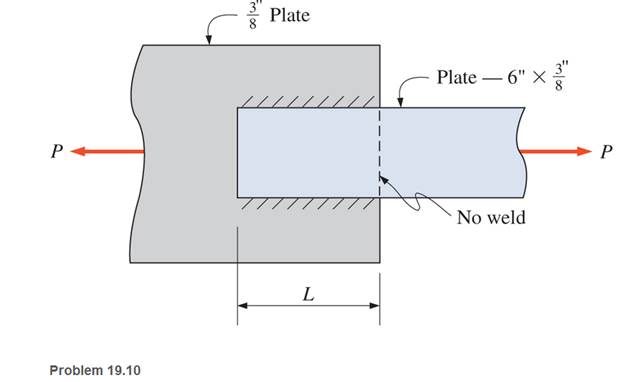
Design the fillet welds parallel to the applied load to develop the full allowable tensile load of the

Learn your wayIncludes step-by-step video

Chapter 19 Solutions
Applied Statics and Strength of Materials (6th Edition)
Additional Engineering Textbook Solutions
Thinking Like an Engineer: An Active Learning Approach (3rd Edition)
Manufacturing Engineering & Technology
Automotive Technology: Principles, Diagnosis, and Service (5th Edition)
Engineering Mechanics: Dynamics (14th Edition)
Automotive Technology: Principles, Diagnosis, And Service (6th Edition) (halderman Automotive Series)
INTERNATIONAL EDITION---Engineering Mechanics: Statics, 14th edition (SI unit)


- Q1: The weldment shown in the figure is subjected to a force F. The hot-rolled steel bar has a thickness h and is of AISI 1040 steel. The vertical support is likewise AISI 1040 HR steel. The electrode is given in the table below. Estimate the static load F the bar can carry if two fillet welds are used. b (mm) h (mm) d (mm) 70 Elecrode E8010 30 6 b→→ Farrow_forwardQ1: The weldment shown in the figure is subjected to a force F. The hot-rolled steel bar has a thickness h and is of AISI 1040 steel. The vertical support is likewise AISI 1040 HR steel. The electrode is given in the table below. Estimate the static load F the bar can carry if two fillet welds are used. b (mm) h (mm) d (mm) 70 Elecrode E8010 30 4arrow_forwardQ1: The weldment shown in the figure is subjected to a force F. The hot-rolled steel bar has a thickness h and is of AISI 1040 steel. The vertical support is likewise AISI 1040 HR steel. The electrode is given in the table below. Estimate the static load F the bar can carry if two fillet welds are used. d (mm) h (mm) Elecrode b (mm) 30 70 6 E8010 4 ko →arrow_forward
- 3.) The diagram below shows a 5.5m long double angle brace which is connected by 6mm welding connection. The length of weld shown in the picture is 300 mm on the top and 100 mm on the bottom. The 2-L127x 89x6.4 are 300W steel and long leg back-to-back. The braces are to be welded to a 12 mm 350W steel gusset plate. Determine the factored tensile capacity of the angles. Any intermediate connections that are required should also be specified. 740 kN -12 mm Gusset Platearrow_forwardSituation 2: The lap splice shown will develop a full strength as shown in the figure. Using E70 electrodes. The width of the plate is 150 mm and the thickness is 10 mm. Use Fy = 248 MPa T4 46 mm 48 mm 1. Which of the following nearly gives the diameter of the slot weld using the LRFD method. O 45 mm T O 47 mm T Warrow_forwardAn angle iron made of AISI 1040 CD steel is welded to metal as shown and loaded with a dynamic load varying between +40kN and +60kN. E70XX (Sut = 482MPa, Sy = 393MPa) will be used as the welding electrode. Find the factor of safety of the weld zone. Note: that both static and dynamic loads are applied to the source.arrow_forward
- The weldment shown in the figure is subjected to a static force of 100 kN. The hot-rolled steel bar has a thickness h=6 mm and is of AISI 1015 HR steel. The vertical support is AISI 1015 HR steel. The electrode is given in the table below. Use the welding code method. (a) is the weld metal strength satisfactory? (b) Is the attachment strength satisfactory? h h=6 mm b=60 mm d=90mm electrode=E6010 |-b- h Farrow_forward200 mm 300 mm 42818 N B = 60° A lifting lug is to be mounted. The lug is shown on the drawing and the force is expected on the lug. The lug has a thickness of 30 mm. Calculate the minimum size of the weld for the given load case to ensure a minimum FOS of 3. Assume an AWS number E70xx electrode is used.arrow_forwardThe weldment shown in Figure 2 is subjected to an alternating force F. The hot-rolled steel bar is 10 mm thick and is of AISI 1010 steel. The vertical support is likewise of 1010 steel. The electrode is 6010. (a) Estimate the fatigue load F the bar will carry if three 6-mm fillet welds are used. 6. 6 50 F -60 Dimensions in millimetersarrow_forward
- 1/2-inch thick steel bar is welded to the vertical supportA) Calculate the allowable load if the electrode is E7018, the bar is 1015 cold drawn steel, the support is 1020 cold drawn steel.arrow_forwardTe - Effective throat thickness well in mm = 6 sin45° Consider the following drawing in which plate 1 is welded onto plate 2 as shown for tensile and shear loading. The plates are fillet welded with a weld thickness of 6 mm as shown for a length of 150 mm. The plates have an ultimate strength of 275 MPa and the welding was done with F70 welding electrodes, which possesses an ultimate strength of 483 MPa. Consider a partial factor of safety of 1.7 for the welded joint and determine the design strength of the weld joint, both in tension (Tdw) and in shear (Vdw) due to the forces acting on it. a) Determine the design strength of the following weld in tension ( ) due to vertical forces. b) Determine the design strength of the weld in shear ( ) due to horizontal forces. Attached pic is shear equation for calculation Tension equation for calculation is: Tdw = FyLwte /Ymwarrow_forwardTwo plates, 25 mm thick, are welded together by means of trans verse-fillet welds. The ultimate tensile strength of a weld metal is 415 MPa. The surface finish factor of the weld surface is 0.5, and the size factor is 0.85. The reliability is 90%. Determine the length of the weld if the factor of safety is 2. The transverse force on the welds is 100 kN, which is completely reversed under fatigue loading. Take: A=10mm 25 Toe Р.arrow_forward
 Elements Of ElectromagneticsMechanical EngineeringISBN:9780190698614Author:Sadiku, Matthew N. O.Publisher:Oxford University Press
 Mechanics of Materials (10th Edition)Mechanical EngineeringISBN:9780134319650Author:Russell C. HibbelerPublisher:PEARSON
 Thermodynamics: An Engineering ApproachMechanical EngineeringISBN:9781259822674Author:Yunus A. Cengel Dr., Michael A. BolesPublisher:McGraw-Hill Education
 Control Systems EngineeringMechanical EngineeringISBN:9781118170519Author:Norman S. NisePublisher:WILEY
 Mechanics of Materials (MindTap Course List)Mechanical EngineeringISBN:9781337093347Author:Barry J. Goodno, James M. GerePublisher:Cengage Learning
 Engineering Mechanics: StaticsMechanical EngineeringISBN:9781118807330Author:James L. Meriam, L. G. Kraige, J. N. BoltonPublisher:WILEY