
(a)
Whether a
Answer to Problem 5.15.6P
Adequate
Explanation of Solution
Given:
Total gravity load = 40 psf of roof surface

Formula used:
Lpis unbraced length in an inelastic behavior
Lris unbraced length in an elastic behavior
Mn is nominal moment strength
Mpis plastic moment capacity
Calculation:
Determine the nominal flexural strength about x and y axes:
Neither the beam design charts nor the Z tables include shapes smaller than W8, so the flexural strength of the
From the dimensions and properties tables, the shape is compact.
The following properties of a
A is Cross-sectional area
Sxis Elastic section modulus about X -axis
Zxis Plastic section modulus about X -axis
Iyis Moment of inertia about Y -axis
ryis Radius of gyration about Y -axis
Syis Elastic section modulus about Y -axis
Cwis Warping constant
h0is Distance between centroid of flanges
J is Torsional moment of inertia
For
From the below given figure in the textbook,

For the y axis, since the shape is compact, there is no flange local buckling
Check the upper limit:
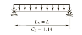
Roof load: Combination 3 controls
where,D is dead load and S is snow load

Tributary width =
Purlin load =
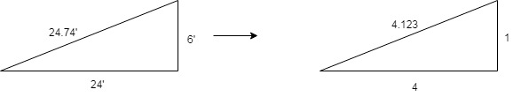
Component normal to roof =
Component parallel to roof =
Calculate factored bending moment about x axis and y axis
Use ½ of weak-axis bending strength in the interaction equation:
Conclusion:
(b)
Whether a
Answer to Problem 5.15.6P
Adequate
Explanation of Solution
Given:
Total gravity load = 40 psf of roof surface
Formula used:
Lpis unbraced length in an inelastic behavior
Lris unbraced length in an elastic behavior
Mn is nominal moment strength
Mpis plastic moment capacity
Calculation:
Determine the nominal flexural strength about x and y axes:
Neither the beam design charts nor the Z tables include shapes smaller than W8, so the flexural strength of the
From the dimensions and properties tables, the shape is compact.
The following properties of a
A is Cross-sectional area
Sxis Elastic section modulus about X -axis
Zxis Plastic section modulus about X -axis
Iyis Moment of inertia about Y -axis
ryis Radius of gyration about Y -axis
Syis Elastic section modulus about Y -axis
Cwis Warping constant
h0is Distance between centroid of flanges
J is Torsional moment of inertia
For
From the below given figure in the textbook,
For the y axis, since the shape is compact, there is no flange local buckling
Check the upper limit:
Roof load: Combination 3 controls
where, D is dead load and S is snow load
Tributary width =
Purlin load =
Component normal to roof =
Component parallel to roof =
Calculate factored bending moment about x axis and y axis
Use ½ of weak - axis bending strength in the interaction equation:
Conclusion:
Want to see more full solutions like this?
Chapter 5 Solutions
Steel Design (Activate Learning with these NEW titles from Engineering!)

- Which of the following best gives the purlin load wuy? See loaded purlin. The figure shown has trusses 6m apart with midpoint sag rods and Purlins C150x12.5 spaced 2.5m on center. The roof truss is inclined 1 vertical to 2 horizontal. The weight of roofing materials is 0.9 kPa (includes self wt.), wind load is 0.8 kPa perpendicular to the roof surface, minimum roof live load is 0.6 kPa. Consider the roofing to provide full lateral support of the purlins. F, = 345 mPa. Use the NSCP 2015 specifications. 2. 5m 2.5m 2. 5m roofing Wuy TRUSS TOP CHORD Truss Spacing = 6m Wux Purlins C150x12.5 Purlin Load Wt A kN/m mm^2 mm C150x12.5 0.12 11400 12.7 152 5.1 SECTION dtw by Ix Sx rx ly mm mm^4 mm^3 mm mm^4 mm^3 mm mm^3 mm^3 48 8.7 143 1100 112 48.4 378 65.2 1230 574 Sy ry Zx| Zy mm mm mm O 4.35 kN/m 5.56 kN/m O 25.02 kN.marrow_forwardA. A truss member is made with a pair of 4"x 3" x 3/8" angles with the long legs back to back. The angles are 36 ksi steel and are attached at the connection by a 3/8 in. plate running between the angles. The unbraced length is 12 feet and consider both ends fixed. What is the allowable axial load in compression? In tension? How does the compression capacity change if I connect them with a %" plate in between? Does it change tension capacity? (a) 12 C. A 28 foot column is braced top and bottom about the X-X axis and has K bracing as shown on the Y-Y axis only. It is built of A36 steel and is a W12 x 30 section. Can it support an axial load of 165 kips? State its actual capacity.arrow_forwardExample 3.15 FIGURE 3.32 Fink trusses spaced at 20 feet on centers support W6 x 12 purlins, as shown in Figure 3.32a. The purlins are supported at their midpoints by sag rods. Use A36 steel and design the sag rods and the tie rod at the ridge for the following service loads. Metal deck: Built-up roof: Snow: Purlin weight: 46.6' 2 @ 12' = 24' 4.679 k 46.6 18.17k (b) 2 psf 5 psf 45 18 psf of horizontal projection of the roof surface 12 pounds per foot (lb/ft) of length 112 42' 90' (a) P P 2@ 12' = 24' F R R 12 (c) 45 3' 3' 3' 3' 12' 4.679 k 4.679karrow_forward
- Q4: Calculate the forces induced in members KL, CL, and CB by the 20-ton load on the cantilever truss. M K 26 16' G F D B A -6 panels at 12' 20 tonsarrow_forwardAnswers: AB = kN E AH = kN Determine the force in each member of the loaded truss. All triangles are 3-4-5. Enter a the member is in tension, negative if in compression. BC - kN C 34kN kN BG E 34 kN BH - kN 15 kN BI = kN D B kN kN A E DE kN H G F DF = kN - 4 panels at 8 m- DG = kN DI kN EF = kN FG - kN GH = kNarrow_forward2. Find the force acting in Bar AC, CE, DE, DF & FH of the Truss as shown in the below figure. B F E 1000 ib 1000 b 1000 b A -12 12 -12- -12 RA RBarrow_forward
- Determine the forces in each member of the truss. State wether it is in tension or compression. Draw a diagram of internal forces and present a results summary list. T a 446 a a a 12/2 커arrow_forward5.15-7 The truss shown in Figure P5.15-7 is one of several roof trusses spaced 18 feet apart. Purlins are located at the joints and halfway between the joints. Sag rods are located midway between the trusses. The weight of the roofing materials is 15 psf, and the snow load is 20 psf of horizontal projection of the roof surface. Use LRFD and select a W shape of A992 steel for the purlins. Manual Table 6-2 may be used. 15'-0" 6 @ 15'-0" = 90'-0" an FIGURE P5.15-7arrow_forwardA plate girder must be designed for the conditions shown in Figure P10.7-4. The given loads are factored, and the uniformly distributed load includes a conservative estimate of the girder weight. Lateral support is provided at the ands and at the load points. Use LRFD for that following: a. Select the, flange and web dimensions so that intermediate stiffeners will he required. Use Fy=50 ksi and a total depth of 50 inches. Bearing stiffeners will be used at the ends and at the load points, but do not proportion them. b. Determine the locations of the intermediate stiffeners, but do not proportion them.arrow_forward
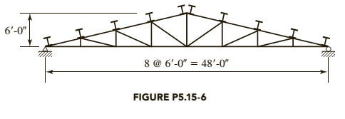
- Q2) The members of the truss structure shown below is plain concrete. The compressive strength of the concrete is 25 MPa. Compute the maximum load P that can be carried by the structure. (Cross section of each member of the truss is 200 x 200 mm and don't use material factors and do not consider slenderness) Comment on your results briefly. P A& 2m SC 2 m 1380 2m Darrow_forwardWhere is/are the location(s) of the maximum transverese shear stress? A simple I-beam is loaded as shown. 20 mm P KN PKN PKN Į Į -C B с D L/4 m L/4 m Midspan at point C Roller at E at the NA Section B at the top fiber Pin A at point C Midspan at point D Roller E at point D L/4 m L/4 m OE 20 mm 20 mm- 250 mm 150 mm 150 mm Aarrow_forwardSOLVE FOR THE FORCE IN ALL MEMBERS OF THE TRUSS. SHOW SOLUTIONS CLEARLY USING METHOD OF JOINTS AND WRITE WELL. 0.8m 2.4m A BD BD 3 KN MEMBER AB AC BC BE BF EF GE FG 2m Av(REACTION @ hinge) Gv(REACTION @ roller) C 1m 10KN B 1m 8KN 3.5m SUMMARY OF RESULTS FORCE E 8KN 1m F 2.4m 6KN G NATURE(T or C)arrow_forward
 Steel Design (Activate Learning with these NEW ti...Civil EngineeringISBN:9781337094740Author:Segui, William T.Publisher:Cengage Learning