
Concept explainers
Videos
The diode in the circuit shown in Figure P1.53 is biased with a constant current source I. A sinusoidal signal
(b) If
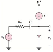
Figure P1.53
Want to see the full answer?
Check out a sample textbook solution
Chapter 1 Solutions
MICROELECT. CIRCUIT ANALYSIS&DESIGN (LL)


- The current through the diode in the circuit given in the Figure below when Vy = 0.7 V is? ww 8092 12V Select one a. 24.26 mA b. 13.09 mA c. 58.23 mA d. 40.13 mA 40-52 ww 3092 IDarrow_forwarduO 9:.0 A docs.google.com * ZAIN IQ l. Q3/B: Assume an ideal diode model for all the diodes in the circuit below. calculate voltages and currents through D1 and D2 9kQ 1N1199C R2 D1 18KQ 1N1199C D3 1N1199C V2 =12 V R3 1kQ R4 5kQ 1.22 V 11 mA 0.5 A O VD1 ID1 VD2 ID2 صفحة 4 من 6arrow_forwardQuestion 1: In the circuit shown below, the output (Vo = 10V Max.) Unipolar. The frequency of Primary is 60 Hz. The diodes are Silicon with VD = 0.7V. a. Sketch the output without a Capacitor. b. Determine Voc without a Capacitor. c. Sketch Vs (at the Secondary). d. Determine Voc with a Capacitor of 10 uF across RL. e. Determine the RMS Value of Vp (at the Primary). f. PIV (Peak Inverse Voltage). 10:1 Output C. 22 k1 All diodes are IN4001. | 00000arrow_forward
- What voltage is boosted at the output of a multiplier.Choices: average, rms, peak, or instantaneous Which assumption is not used in the analysis of multipliers?Choices: a capacitor will not discharge, start with the cycle of the source that will forward bias the nearest diode, the output will always be multiplied, or a single diode is forward biased at a time A voltage multiplierChoices: multiplies the output voltage, has very high voltage and low current ,can employ inductors, or may not have equal numbers of diodes and capacitors A voltage regulator maintains constant voltage at the load regardless of variations atChoices: the input and output, the load, source, or in the environment Between a lower percent regulation and a higher one, which is better?Choices: lower or higherarrow_forwardProblem 3 For the circuit shown below, assume that: R=20kQ, D1, D2, D3 and D4 are modeled by a battery of 0.8 V and rB = 30Q, the Zener diode has 5 V breakdown voltage and rz= 502. 'Vin' is a sinusoidal signal with 1 kHz frequency and amplitude voltage of 15 V: • Sketch 'Vout' and Iz' for -15V< Vin <15V. • Plot 'Vout' and Iz’ versus time • What is the function of this circuit? Vout w- + + D4 D, Vin Darrow_forwardQ4) Determine and sketch the output voltage across the load resistor (RL) for the circuit shown below (assume Si diodes) V_DC V DC 0,75 (1+ 0.25 V_SIN V SIN RL -1 V SOR V_SQR 0.75 -0.75 V TRI 1 V_TRI -1arrow_forward
- A forward voltage of 1.75V shifts to the left at a rate 2.65mV per degree centigrade in temperature from 25°C to -35°C. What is the new forward voltage of the diode? * Your answer Find the reverse saturation current of a Silicon diode that displays a forward current of 20 mA at 0.75 V when the Thermal Voltage is 0.038 V. ( Express your answer in 3 decimal places. Your answer can be in p (pico) or n (nano) unit. e.g. only 5 nV. Upload your solution in the file upload question but type Final Answer here. * Your answerarrow_forwardI ln. l. . :D docs.google.com/forms/d/e/1l Diode clippers are wave-shaping circuits in that they are not used to prevent signal voltage from going above or below certain * .levels TO F like that of the clipper, the shape of the .input signals of a clamper is changed F The clamping circuit clamps or shift the * .input sinusoidal signal up or down FO IIarrow_forwardQ: - Consider the circuit in Figure a) What type of circuit is this? b) Find and Sketch the voltage waveform across RL, assume the diodes are practical. 4:1 D, 120 V rms c) If sin wave with 100µf connected in parallel with the resistor, calculate the ripple сарacitor is 60 HZ 1.0 kN D2 factor lllee lelllarrow_forward
- In the circuit shown below, the ideality factorn of the diode is unity and the voltage drop across it is 0.7 V. The dynamic resistance of the diode at room temperature is approximately 1.7 V 31 k2arrow_forwardThe voltage signal coming out of the capacitor is with small ripples compare to the voltage signal out of the diode. True Falsearrow_forwardSOLVE STEP BY STEP IN DIGITAL FORMAT For each of the circuits shown below, draw its voltage transfer curve, using the constant-drop model (all diodes are silicon identical, V_Don = 0.7V). Consider a variation of the input voltage from -10V to +10V. Vi V₁ D₁ D₁ Z D₂ 1k Circuit 1 1k Circuit 2 V₂ + V₂ Vi Vi 1k 1k D₁ Circuit 3 D₁ 1k ww 1k Circuit 4 + V₂ + V₂arrow_forward
 Introductory Circuit Analysis (13th Edition)Electrical EngineeringISBN:9780133923605Author:Robert L. BoylestadPublisher:PEARSON
 Delmar's Standard Textbook Of ElectricityElectrical EngineeringISBN:9781337900348Author:Stephen L. HermanPublisher:Cengage Learning
 Programmable Logic ControllersElectrical EngineeringISBN:9780073373843Author:Frank D. PetruzellaPublisher:McGraw-Hill Education
 Fundamentals of Electric CircuitsElectrical EngineeringISBN:9780078028229Author:Charles K Alexander, Matthew SadikuPublisher:McGraw-Hill Education
 Electric Circuits. (11th Edition)Electrical EngineeringISBN:9780134746968Author:James W. Nilsson, Susan RiedelPublisher:PEARSON
 Engineering ElectromagneticsElectrical EngineeringISBN:9780078028151Author:Hayt, William H. (william Hart), Jr, BUCK, John A.Publisher:Mcgraw-hill Education,