
Concept explainers
Videos
Repeat Problem 1.47 if the reverse−saturation current for each diode isy
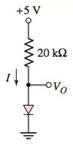
a.
The voltage across diode.
Answer to Problem 1.48P
The diode voltage,
Explanation of Solution
Given information:
The circuit diagram is given as:
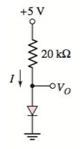
The reverse saturation current for each diode is
Calculation:
The expression for the diode current is given as:
From the given circuit, evaluating the diode current:
From the circuit, the output voltage is same as the diode voltage.
Solving equation 1 and 2 by using the hit and trial method:
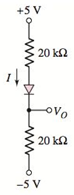
b.
The voltage across diode.
Answer to Problem 1.48P
The diode voltage,
Explanation of Solution
Given information:
The circuit diagram is given as:
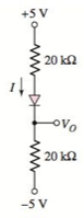
The reverse saturation current for each diode is
Calculation:
The expression for the diode current is given as:
From the given circuit, evaluating the diode current:
Applying the Kirchhoff’s voltage law to the circuit from top to bottom:
Assuming the voltage across diode vD, then applying the Kirchhoff’s voltage law from top to the output voltage:
From the circuit, the diode current is same as the current flowing in the circuit:
Solving equation 1, 2 and 3 by using the hit and trial method:
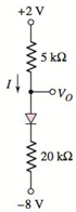
c.
The voltage across diode.
Answer to Problem 1.48P
The diode voltage,
Explanation of Solution
Given information:
The circuit diagram is given as:
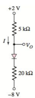
The reverse saturation current for each diode is
Calculation:
The expression for the diode current is given as:
From the given circuit, evaluating the diode current:
Applying the Kirchhoff’s voltage law to the circuit from top to bottom:
Then applying the Kirchhoff’s voltage law from top to the output voltage:
From the circuit, the diode current is same as the current flowing in the circuit:
Solving equation 1, 2 and 3 by using the hit and trial method:
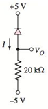
d.
The voltage across diode.
Answer to Problem 1.48P
The diode voltage,
Explanation of Solution
Given information:
The circuit diagram is given as:
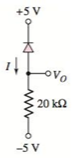
The reverse saturation current for each diode is
Calculation:
Referring the given circuit, here the diode current is flowing in the reverse direction.
Hence, the reverse saturation current will be the diode current in this case.
Since the value of the reverse saturation current is given in the question.
Therefore,
Now evaluating the diode voltage:
Since, due to reverse direction of the current, no current will flow through the resistor. Hence the drop across the resistor will be zero.
Therefore, the value of the diode voltage will be same as the output voltage:
Want to see more full solutions like this?
Chapter 1 Solutions
MICROELECT. CIRCUIT ANALYSIS&DESIGN (LL)


- How is a solid-state diode tested? Explain.arrow_forwardIn the circuit given in the figure, find the current passing through the diode in mA since R1 = 4.95Kohm, R2 = 2.50Kohm, R3 = 1.69Kohm, R4 = 5.44Kohm, VCC = 13.00V and the diode is silicon?arrow_forwardConsider the circuit in the figure below 4:1 120 V rms ooooo gll reelee D₁ L a. What type of circuit is this? b. What is the total peak secondary voltage? D₂ c. Find the peak voltage across each half of the secondary. d. Sketch the voltage waveform across RL. e. What is the peak current through each diode? f. What is the PIV for each diode? RL 1.0 ΚΩarrow_forward
- Determine the negative resistance for the tunnel diode in the figure between ?T = 0.2 ? and ?T = 0.4arrow_forwardDraw output waveform for the following circuit. Suppose input is a pure square wave with a positive half at 10 V and negative half at -10 V for ideal diodes. D1 D2 220 R3 R1 1k R2 1karrow_forwardQ: Using the ideal model for the diode. what Current I in milliamps if V₁ = 1.0 Volts and V₂ = 7.0 Volts? V₁0 V₂0 DI 艹 Dz K 。V il $2k12 -3varrow_forward
- (c) Reverse recovery is a common problem in a diode. It can increase switching losses, increase forward voltage and induce voltage surge. (i) Explain how reverse recovery can increase switching losses in a diode. (ii) Figure Q1(c) shows that characteristic of reverse recovery in a diode. Based on the figure, calculate the peak reverse recovery current I, I (A) dls dt 30 A Q,, 1 us 3 us Figure Q1(c): The characteristic of reverse recovery in a diodearrow_forwardA zener diode exhibits a certain change in VZ for a certain change in IZ on a portion of the linear characteristic curve between IZK and IZM as illustrated in Figure 5. Calculate the zener impedance.arrow_forwardQ#1: What is Diode? Explain the Forward Biasing of Diode in detail.arrow_forward
- A- If V, is a sinusoidal voltage with Vm = 40 V, and V= 15 V. Plot the waveform of the output voltage in each of the following clippers circuits assuming ideal diodes. B- Repeat part (A) if the diodes are silicon diodes. R R R (a) (b) (c) (d)arrow_forwardFor the circuit below, assume the diodes operate with a constant voltage drop of .7V, find Vx, Vy, VD4 and ID2. 15V 15V Allt V1 V2 R1 1k IDC 1mA Vx R2 2k ww D1N4002 Vy D1N4002 7D1 D1N4002 D2 D3 R3 1k D4 D1N4002arrow_forwardJunction Diode Give the following details of the diode: Schematic symbol Construction Characteristic Curve Basic operation (including mathematical equation if there's any) Applicationsarrow_forward
