
Mechanics of Materials
11th Edition
ISBN: 9780137605460
Author: Russell C. Hibbeler
Publisher: Pearson Education (US)
expand_more
expand_more
format_list_bulleted
Concept explainers
Videos
Textbook Question
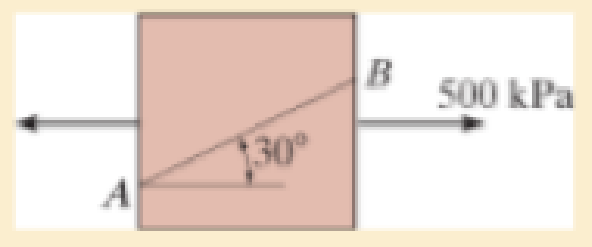
Chapter 9.4, Problem 7FP
Use Mohr’s circle to determine the normal stress and shear stress acting on the inclined plane AB.
Expert Solution & Answer

Learn your wayIncludes step-by-step video

schedule03:52
Students have asked these similar questions
Use Mohr's Circle to determine the maximum shear stress on the element, also using Mohr's Circle determine the maximum normal stress on the element.
Determine the absolute shear stress for point K.
Determine the normal stress and shear stress acting on the inclined plane AB. Sketch the result on the sectioned element.
Chapter 9 Solutions
Mechanics of Materials
Ch. 9.3 - Determine the normal stress and shear stress...Ch. 9.3 - Determine the equivalent state of stress on an...Ch. 9.3 - Also, find the corresponding orientation of the...Ch. 9.3 - Determine the equivalent state of stress on an...Ch. 9.3 - Determine the maximum principal stress at point B.Ch. 9.3 - Determine the principal stress at point C.Ch. 9.3 - Determine the stress components acting on the...Ch. 9.3 - Solve Prob.99 using the stress transformation...Ch. 9.3 - Determine the stress components acting on the...Ch. 9.3 - Determine the equivalent state of stress on an...
Ch. 9.3 - The stress along two planes at a point is...Ch. 9.3 - The state of stress at a point in a member is...Ch. 9.3 - The wood beam is subjected to a load of 12 kN. If...Ch. 9.3 - The internal loadings at a section of the beam are...Ch. 9.3 - Solve Prob.925 for point B. 925. The internal...Ch. 9.3 - Solve Prob.925 for point C. 925. The internal...Ch. 9.3 - It is subjected to a torque of 12 kip in. and a...Ch. 9.3 - A paper tube is formed by rolling a cardboard...Ch. 9.3 - Solve Prob.931 for the normal stress acting...Ch. 9.3 - Determine the principal stresses in the...Ch. 9.3 - The shaft has a diameter d and is subjected to the...Ch. 9.4 - Use Mohrs circle to determine the normal stress...Ch. 9.4 - Also, find the corresponding orientation of the...Ch. 9.4 - Draw Mohrs circle and determine the principal...Ch. 9.4 - Determine the principal stresses at a point on the...Ch. 9.4 - Determine the principal stresses at point A on the...Ch. 9.4 - Point A is just below the flange.Ch. 9.4 - Mohrs circle for the state of stress is shown in...Ch. 9.4 - Determine (a) the principal stresses and (b) the...Ch. 9.4 - Determine the equivalent state of stress if an...Ch. 9.4 - Draw Mohrs circle that describes each of the...Ch. 9.4 - Draw Mohrs circle trial describes each of the...Ch. 9.4 - Determine (a) the principal stresses and (b) the...Ch. 9.4 - Determine (a) the principal stresses and (b) the...Ch. 9.4 - Draw Mohrs circle that describes each of the...Ch. 9.4 - The grains of wood in the board make an angle of...Ch. 9.4 - A spherical pressure vessel has an inner radius of...Ch. 9.4 - The cylindrical pressure vessel has an inner...Ch. 9.4 - If the box wrench is subjected to the 50 lb force,...Ch. 9.4 - If the box wrench is subjected to the 50-lb force,...Ch. 9.5 - Draw the three Mohrs circles that describe each of...Ch. 9.5 - Draw the three Mohrs circles that describe the...Ch. 9.5 - Determine the principal stresses and the absolute...Ch. 9.5 - The solid shaft is subjected to a torque, bending...Ch. 9.5 - The frame is subjected to a horizontal force and...Ch. 9 - Prob. 1RPCh. 9 - The steel pipe has an inner diameter of 2.75 in....Ch. 9 - Determine the equivalent state of stress If an...Ch. 9 - The crane is used to support the 350-lb load....Ch. 9 - Determine the equivalent state of stress on an...Ch. 9 - The propeller shaft of the tugboat is subjected to...Ch. 9 - Determine the principal stresses in the box beam...Ch. 9 - Determine (a) the principal stresses and (b) the...Ch. 9 - Determine the stress components acting on the...
Additional Engineering Textbook Solutions
Find more solutions based on key concepts
If FB = 30 lb and FC = 45 lb, determine the resultant moment about the bolt located at A. Probs. 49/10
Engineering Mechanics: Statics
The data shown in the following graph was collected during testing of an electromagnetic mass driver. The energ...
Thinking Like an Engineer: An Active Learning Approach (4th Edition)
Figure 3.24 shows a closed container holding water and oil. Air at 34 kPa below atmosperic pressure is above th...
Applied Fluid Mechanics (7th Edition)
What parts are included in the vehicle chassis?
Automotive Technology: Principles, Diagnosis, and Service (5th Edition)
The copper pipe has an outer diameter of 40 mm and an inner diameter of 37 mm. If it is tightly secured to the ...
Statics and Mechanics of Materials (5th Edition)
3.7 The 150-lb force shown is the resultant of two forces, one of which is shown. Determine the other force.
Applied Statics and Strength of Materials (6th Edition)
Knowledge Booster


Learn more about
Need a deep-dive on the concept behind this application? Look no further. Learn more about this topic, mechanical-engineering and related others by exploring similar questions and additional content below.Similar questions
- The plate has a thickness of 20 mm and the force P = 3 kN acts along the centerline of this thickness such that d = 150 mm. Plot the distribution of normal stress acting along section a–a.arrow_forwardThe box beam is subjected to the 26-kN force that is applied at the center of its width, 75 mm from each side. Determine the principal stresses at point A and show the results in an element located at this point. Use the shear formula to calculate the shear stress.arrow_forwardThe average normal stress and maximum in-plane shear stress components are determined from the circle as the coordinates of either point. true or false?arrow_forward
- 2. determine the maximum normal stress and the maximum shear stress at point O in dia. B 15 in 7 in F = 15 lbfarrow_forwardThe hook is subjected to the force of 80 lb. Determine the state of stress at point B at section a–a. The cross section has a diameter of 0.5 in. Use the curved-beam formula to calculate the bending stress.arrow_forwardDetermine the principal stress and absolute maximum shear stress developed at point B on the cross section of the bracket at section a-a. Show the Mohr's circle for point B. -300 mm 150 mm 2.5 kN a 12 mm B 6 mm www 6 mm 5 4 A, 36 mm'36 mm Section a - a 6 mmarrow_forward
- In each case, the state of stress sx, sy, txy produces normal and shear stress components along section AB of the element that have values of sx = -5 kPa and tx y = 8 kPa when calculated using the stress transformation equations.Establish the x and y axes for each segment and specify the angle u, then show these results acting on each segment.arrow_forwardIf the allowable normal stress is 120MPa and the allowable shear stress is 60MPa, what is the resultant force at the support A?arrow_forwardDetermine Value of x if the Normal stress at rod is equal to the stress at rectangular pipe A =400 mm2 F = 8kN Rod A =650 mm2 rectangular Pipearrow_forward
- The 0.97 in diameter rod is subjected to the loads shown. Determine the normal and shear stress at point B.arrow_forwardThe horizontal force of P = 80 KN acts at the end of the plate. The plate has a thickness of 10 mm and P acts along the centerline of this thickness such that d = 50 mm. Plot the distribution of normal stress acting along section a-a.arrow_forwardDetermine the normal stress and shear stress acting on the inclined plane AB. Solve the problem using the stress transformation equations. Show the results on the sectional element.arrow_forward
arrow_back_ios
SEE MORE QUESTIONS
arrow_forward_ios
Recommended textbooks for you
 Elements Of ElectromagneticsMechanical EngineeringISBN:9780190698614Author:Sadiku, Matthew N. O.Publisher:Oxford University Press
 Mechanics of Materials (10th Edition)Mechanical EngineeringISBN:9780134319650Author:Russell C. HibbelerPublisher:PEARSON
 Thermodynamics: An Engineering ApproachMechanical EngineeringISBN:9781259822674Author:Yunus A. Cengel Dr., Michael A. BolesPublisher:McGraw-Hill Education
 Control Systems EngineeringMechanical EngineeringISBN:9781118170519Author:Norman S. NisePublisher:WILEY
 Mechanics of Materials (MindTap Course List)Mechanical EngineeringISBN:9781337093347Author:Barry J. Goodno, James M. GerePublisher:Cengage Learning
 Engineering Mechanics: StaticsMechanical EngineeringISBN:9781118807330Author:James L. Meriam, L. G. Kraige, J. N. BoltonPublisher:WILEY
Elements Of Electromagnetics
Mechanical Engineering
ISBN:9780190698614
Author:Sadiku, Matthew N. O.
Publisher:Oxford University Press
Mechanics of Materials (10th Edition)
Mechanical Engineering
ISBN:9780134319650
Author:Russell C. Hibbeler
Publisher:PEARSON
Thermodynamics: An Engineering Approach
Mechanical Engineering
ISBN:9781259822674
Author:Yunus A. Cengel Dr., Michael A. Boles
Publisher:McGraw-Hill Education
Control Systems Engineering
Mechanical Engineering
ISBN:9781118170519
Author:Norman S. Nise
Publisher:WILEY
Mechanics of Materials (MindTap Course List)
Mechanical Engineering
ISBN:9781337093347
Author:Barry J. Goodno, James M. Gere
Publisher:Cengage Learning
Engineering Mechanics: Statics
Mechanical Engineering
ISBN:9781118807330
Author:James L. Meriam, L. G. Kraige, J. N. Bolton
Publisher:WILEY
Understanding Stress Transformation and Mohr's Circle; Author: The Efficient Engineer;https://www.youtube.com/watch?v=_DH3546mSCM;License: Standard youtube license