
Mechanics of Materials
11th Edition
ISBN: 9780137605460
Author: Russell C. Hibbeler
Publisher: Pearson Education (US)
expand_more
expand_more
format_list_bulleted
Concept explainers
Videos
Textbook Question
Chapter 9, Problem 2RP
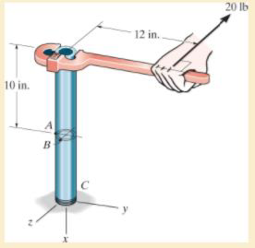
The steel pipe has an inner diameter of 2.75 in. and an outer diameter of 3 in. If it is fixed at C and subjected to the horizontal 20-lb force acting on the handle of the pipe wrench, determine the principal stresses in the pipe at point B, which is located on the surface of the pipe.
Expert Solution & Answer
Want to see the full answer?
Check out a sample textbook solution
Students have asked these similar questions
The steel pipe has an inner diameter of 2.75 in. and an outer diameter of 3 in. If it is fixed at C and subjected to the horizontal 60-lb force acting on the handle of the pipe wrench at its end, determine the principal stresses in the pipe at point A, which is located on the outer surface of the pipe.
The steel tube below has an inside diameter of 2.75”, and an outside diameter of 3”. If the tube is fixed at C, and subjected to the 20 lb horizontal force acting on the wrench as shown, determine the principal stresses in the point A, which is located on the surface of the tube
If the box wrench is subjected to the 50-lb force, determine the principal stresses and maximum in-plane shear stress at point B on the cross section of the wrench at section a–a. Specify the orientation of these states of stress and indicate the results on elements at the point.
Chapter 9 Solutions
Mechanics of Materials
Ch. 9.3 - Determine the normal stress and shear stress...Ch. 9.3 - Determine the equivalent state of stress on an...Ch. 9.3 - Also, find the corresponding orientation of the...Ch. 9.3 - Determine the equivalent state of stress on an...Ch. 9.3 - Determine the maximum principal stress at point B.Ch. 9.3 - Determine the principal stress at point C.Ch. 9.3 - Determine the stress components acting on the...Ch. 9.3 - Solve Prob.99 using the stress transformation...Ch. 9.3 - Determine the stress components acting on the...Ch. 9.3 - Determine the equivalent state of stress on an...
Ch. 9.3 - The stress along two planes at a point is...Ch. 9.3 - The state of stress at a point in a member is...Ch. 9.3 - The wood beam is subjected to a load of 12 kN. If...Ch. 9.3 - The internal loadings at a section of the beam are...Ch. 9.3 - Solve Prob.925 for point B. 925. The internal...Ch. 9.3 - Solve Prob.925 for point C. 925. The internal...Ch. 9.3 - It is subjected to a torque of 12 kip in. and a...Ch. 9.3 - A paper tube is formed by rolling a cardboard...Ch. 9.3 - Solve Prob.931 for the normal stress acting...Ch. 9.3 - Determine the principal stresses in the...Ch. 9.3 - The shaft has a diameter d and is subjected to the...Ch. 9.4 - Use Mohrs circle to determine the normal stress...Ch. 9.4 - Also, find the corresponding orientation of the...Ch. 9.4 - Draw Mohrs circle and determine the principal...Ch. 9.4 - Determine the principal stresses at a point on the...Ch. 9.4 - Determine the principal stresses at point A on the...Ch. 9.4 - Point A is just below the flange.Ch. 9.4 - Mohrs circle for the state of stress is shown in...Ch. 9.4 - Determine (a) the principal stresses and (b) the...Ch. 9.4 - Determine the equivalent state of stress if an...Ch. 9.4 - Draw Mohrs circle that describes each of the...Ch. 9.4 - Draw Mohrs circle trial describes each of the...Ch. 9.4 - Determine (a) the principal stresses and (b) the...Ch. 9.4 - Determine (a) the principal stresses and (b) the...Ch. 9.4 - Draw Mohrs circle that describes each of the...Ch. 9.4 - The grains of wood in the board make an angle of...Ch. 9.4 - A spherical pressure vessel has an inner radius of...Ch. 9.4 - The cylindrical pressure vessel has an inner...Ch. 9.4 - If the box wrench is subjected to the 50 lb force,...Ch. 9.4 - If the box wrench is subjected to the 50-lb force,...Ch. 9.5 - Draw the three Mohrs circles that describe each of...Ch. 9.5 - Draw the three Mohrs circles that describe the...Ch. 9.5 - Determine the principal stresses and the absolute...Ch. 9.5 - The solid shaft is subjected to a torque, bending...Ch. 9.5 - The frame is subjected to a horizontal force and...Ch. 9 - Prob. 1RPCh. 9 - The steel pipe has an inner diameter of 2.75 in....Ch. 9 - Determine the equivalent state of stress If an...Ch. 9 - The crane is used to support the 350-lb load....Ch. 9 - Determine the equivalent state of stress on an...Ch. 9 - The propeller shaft of the tugboat is subjected to...Ch. 9 - Determine the principal stresses in the box beam...Ch. 9 - Determine (a) the principal stresses and (b) the...Ch. 9 - Determine the stress components acting on the...
Additional Engineering Textbook Solutions
Find more solutions based on key concepts
The moment of inertia Iy for the slender rod in terms of the rod’s total mass m .
Engineering Mechanics: Statics & Dynamics (14th Edition)
What is the importance of modeling in engineering? How are the mathematical models for engineering processes pr...
HEAT+MASS TRANSFER:FUND.+APPL.
A 20-lb force is applied to the control rod AB as shown. Knowing that the length of the rod is 9 in. and that t...
Statics and Mechanics of Materials
The triple jump is a track-and-field event in which an athlete gets a running start and tries to leap as far as...
Vector Mechanics For Engineers
3.3 It is known that a vertical force of 200 lb is required to remove the nail at C from the board. As the nail...
Vector Mechanics for Engineers: Statics, 11th Edition
Assume the following vectors are already defined: V1=[302]V2=[214]V3=[5131]V4=[0.50.10.20.2] For each of the fo...
Thinking Like an Engineer: An Active Learning Approach (4th Edition)
Knowledge Booster


Learn more about
Need a deep-dive on the concept behind this application? Look no further. Learn more about this topic, mechanical-engineering and related others by exploring similar questions and additional content below.Similar questions
- Determine the shortest distance d to the edge of the plate at which the force P can be applied so that it produces no compressive stresses in the plate at section a–a. The plate has a thickness of 10 mm and P acts along the centerline of this thickness.arrow_forwardDetermine the maximum distance d to the edge of the plate at which the force P can be applied so that it produces no compressive stresses on the plate at section a–a. The plate has a thickness of 20 mm and P acts along thecenterline of this thickness.arrow_forwardThe tank of the air compressor is subjected to an internal pressure of 90 psi. If the inner diameter of the tank is 22 in., and the wall thickness is 0.25 in., determine the stress components acting at point A. Draw a volume element of the material at this point, and show the results on the element.arrow_forward
- The clamp presses the smooth surface at E when tightening the screw. If the tension in the bolt is 40 kN, determine the principal stress at points A and B and show the results on the elements located at each of these points. The cross-sectional area at A and B is shown in the adjacent figure. 300 mm 50 mm 30 mm 100 mm B 25 mm A 100 mm -50 mmarrow_forwardAir pressure in the cylinder is increased by exerting forces P = 2 kN on the two pistons, each having a radius of 45 mm. If the cylinder has a wall thickness of 2 mm, determine the state of stress in the wall of the cylinder.arrow_forwardThe bolt is fixed to its support at C. If a force of 18 lb is applied to the wrench to tighten it, determine the principal stresses and the absolute maximum shear stress in the bolt shank at point A. Represent the results on an elementlocated at this point. The shank has a diameter of 0.25 in.arrow_forward
- The propeller shaft of the tugboat is subjected to the compressive force and torque shown. If the shaft has an inner diameter of 100 mm and an outer diameter of 150 mm, determine the principal stresses at a point A located on the outer surface.arrow_forwardThe copper pipe has an outer diameter of 2.50 in. and an inner diameter of 2.30 in. If it is tightly secured to the wall and three torques are applied to it, determine the shear stress developed at points A and B. These points lie on the pipe’s outer surface. Sketch the shear stress on volume elements located at A and B.arrow_forwardThe steel pipe in (Figure 1) has an inner diameter of 3.41 in and an outer diameter of 3.66 in. If it is fixed at C and subjected to the horizontal 60-lb force acting on the handle of the pipe wrench at its end, determine the principal stresses in the pipe at point A, which is located on the outer surface of the pipe.arrow_forward
- The steel bracket is used to connect the ends of two cables. If the applied force P = 1.50 kip, determine the maximum normal stress in the bracket. Assume the bracket is a rod having a diameter of 1.5 in.arrow_forwardQ2: If the block is subjected to the centrally applied force of 600 kN, determine the average normal stress in the material. Show the stress acting on a differential volume element of the material. 150 mm 150 mm 150 mm 150 mm 600 KN 50 mm 100 mm 100 mm 50 mmarrow_forwardThe bent shaft is fixed in the wall at A. If a force F is applied at B (the force is acting on the plane parallel to the x-o-y plane). Take F = 54 N and 0 = 45°. 1. Determine the internal forces acting on the section containing points D and E 2. Determine the normal stress component acting at point E 3. Determine the shear stress component developed at point E 4. Draw the state of stress on a volume element (stress element) located at point E 5. Determine the principal stresses acting at point E by constructing Mohr's circle A 150 mm E 200 mm 30 mm 75 mm B Farrow_forward
arrow_back_ios
SEE MORE QUESTIONS
arrow_forward_ios
Recommended textbooks for you
 Elements Of ElectromagneticsMechanical EngineeringISBN:9780190698614Author:Sadiku, Matthew N. O.Publisher:Oxford University Press
 Mechanics of Materials (10th Edition)Mechanical EngineeringISBN:9780134319650Author:Russell C. HibbelerPublisher:PEARSON
 Thermodynamics: An Engineering ApproachMechanical EngineeringISBN:9781259822674Author:Yunus A. Cengel Dr., Michael A. BolesPublisher:McGraw-Hill Education
 Control Systems EngineeringMechanical EngineeringISBN:9781118170519Author:Norman S. NisePublisher:WILEY
 Mechanics of Materials (MindTap Course List)Mechanical EngineeringISBN:9781337093347Author:Barry J. Goodno, James M. GerePublisher:Cengage Learning
 Engineering Mechanics: StaticsMechanical EngineeringISBN:9781118807330Author:James L. Meriam, L. G. Kraige, J. N. BoltonPublisher:WILEY
Elements Of Electromagnetics
Mechanical Engineering
ISBN:9780190698614
Author:Sadiku, Matthew N. O.
Publisher:Oxford University Press
Mechanics of Materials (10th Edition)
Mechanical Engineering
ISBN:9780134319650
Author:Russell C. Hibbeler
Publisher:PEARSON
Thermodynamics: An Engineering Approach
Mechanical Engineering
ISBN:9781259822674
Author:Yunus A. Cengel Dr., Michael A. Boles
Publisher:McGraw-Hill Education
Control Systems Engineering
Mechanical Engineering
ISBN:9781118170519
Author:Norman S. Nise
Publisher:WILEY
Mechanics of Materials (MindTap Course List)
Mechanical Engineering
ISBN:9781337093347
Author:Barry J. Goodno, James M. Gere
Publisher:Cengage Learning
Engineering Mechanics: Statics
Mechanical Engineering
ISBN:9781118807330
Author:James L. Meriam, L. G. Kraige, J. N. Bolton
Publisher:WILEY
Pressure Vessels Introduction; Author: Engineering and Design Solutions;https://www.youtube.com/watch?v=Z1J97IpFc2k;License: Standard youtube license