
Mechanics of Materials
11th Edition
ISBN: 9780137605460
Author: Russell C. Hibbeler
Publisher: Pearson Education (US)
expand_more
expand_more
format_list_bulleted
Concept explainers
Videos
Textbook Question
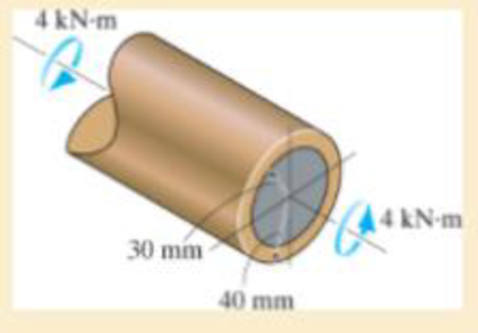
Chapter 9.4, Problem 10FP
Determine the principal stresses at a point on the surface of the shaft.
Expert Solution & Answer
Want to see the full answer?
Check out a sample textbook solution
Students have asked these similar questions
The element in the image has a horizontal force of 20 N and a vertical force of 25 N. The element was made of a 25.4 mm diameter steel bar. Determine:to. The four states of stress from the farthest place of the forces and obtain the critical point.b. For the critical point, construct the Mohr circle.C. Obtain the maximum principal and normal shear stresses for the critical point.d. The angles at which the maximum normal and shear stresses occur.and. Draw the rotated tension state for the angles obtained and with the corresponding tensions.
Calculate the normal stresses at points A and B of the bracket caused by the 30-kN force.
IN THE SYSTEM SHOWN AS BELOW, A FORCE OF 200 N AFFECTS ON THE PIPE SWITCH. CONSISTING AT POINTS A AND B ON THE PIPE ACCORDING THAT THE PIPE'S DIAMETER IS 25 mm;
SHOW THE PRIMARY STRESSES AND PRIME AXES (principal axis directions) ON THE MOHR CIRCLE.
Chapter 9 Solutions
Mechanics of Materials
Ch. 9.3 - Determine the normal stress and shear stress...Ch. 9.3 - Determine the equivalent state of stress on an...Ch. 9.3 - Also, find the corresponding orientation of the...Ch. 9.3 - Determine the equivalent state of stress on an...Ch. 9.3 - Determine the maximum principal stress at point B.Ch. 9.3 - Determine the principal stress at point C.Ch. 9.3 - Determine the stress components acting on the...Ch. 9.3 - Solve Prob.99 using the stress transformation...Ch. 9.3 - Determine the stress components acting on the...Ch. 9.3 - Determine the equivalent state of stress on an...
Ch. 9.3 - The stress along two planes at a point is...Ch. 9.3 - The state of stress at a point in a member is...Ch. 9.3 - The wood beam is subjected to a load of 12 kN. If...Ch. 9.3 - The internal loadings at a section of the beam are...Ch. 9.3 - Solve Prob.925 for point B. 925. The internal...Ch. 9.3 - Solve Prob.925 for point C. 925. The internal...Ch. 9.3 - It is subjected to a torque of 12 kip in. and a...Ch. 9.3 - A paper tube is formed by rolling a cardboard...Ch. 9.3 - Solve Prob.931 for the normal stress acting...Ch. 9.3 - Determine the principal stresses in the...Ch. 9.3 - The shaft has a diameter d and is subjected to the...Ch. 9.4 - Use Mohrs circle to determine the normal stress...Ch. 9.4 - Also, find the corresponding orientation of the...Ch. 9.4 - Draw Mohrs circle and determine the principal...Ch. 9.4 - Determine the principal stresses at a point on the...Ch. 9.4 - Determine the principal stresses at point A on the...Ch. 9.4 - Point A is just below the flange.Ch. 9.4 - Mohrs circle for the state of stress is shown in...Ch. 9.4 - Determine (a) the principal stresses and (b) the...Ch. 9.4 - Determine the equivalent state of stress if an...Ch. 9.4 - Draw Mohrs circle that describes each of the...Ch. 9.4 - Draw Mohrs circle trial describes each of the...Ch. 9.4 - Determine (a) the principal stresses and (b) the...Ch. 9.4 - Determine (a) the principal stresses and (b) the...Ch. 9.4 - Draw Mohrs circle that describes each of the...Ch. 9.4 - The grains of wood in the board make an angle of...Ch. 9.4 - A spherical pressure vessel has an inner radius of...Ch. 9.4 - The cylindrical pressure vessel has an inner...Ch. 9.4 - If the box wrench is subjected to the 50 lb force,...Ch. 9.4 - If the box wrench is subjected to the 50-lb force,...Ch. 9.5 - Draw the three Mohrs circles that describe each of...Ch. 9.5 - Draw the three Mohrs circles that describe the...Ch. 9.5 - Determine the principal stresses and the absolute...Ch. 9.5 - The solid shaft is subjected to a torque, bending...Ch. 9.5 - The frame is subjected to a horizontal force and...Ch. 9 - Prob. 1RPCh. 9 - The steel pipe has an inner diameter of 2.75 in....Ch. 9 - Determine the equivalent state of stress If an...Ch. 9 - The crane is used to support the 350-lb load....Ch. 9 - Determine the equivalent state of stress on an...Ch. 9 - The propeller shaft of the tugboat is subjected to...Ch. 9 - Determine the principal stresses in the box beam...Ch. 9 - Determine (a) the principal stresses and (b) the...Ch. 9 - Determine the stress components acting on the...
Additional Engineering Textbook Solutions
Find more solutions based on key concepts
Three rigid bodies, 2,3, and 4, are connected by four springs as shown in the figure. A horizontal force of 1,0...
Introduction To Finite Element Analysis And Design
A pipe flowing light oil has a manometer attached, as shown in Fig, P1.52. What is the absolute pressure in pip...
Fundamentals Of Thermodynamics
Convert the following quantities from English to SI units: a. 98 Btu/(hr-ft-F) b. 0.24 Btu/(lbm-F) C. 0.04 Ibm/...
Heating Ventilating and Air Conditioning: Analysis and Design
What types of polymers are most commonly blow molded?
Degarmo's Materials And Processes In Manufacturing
How is the hydrodynamic entry length defined for flow in a pipe? Is the entry length longer in laminar or turbu...
Fluid Mechanics Fundamentals And Applications
For the beam loading of Figure P334, draw the complete shearing force and bending moment diagrams, and determin...
Machine Elements in Mechanical Design (6th Edition) (What's New in Trades & Technology)
Knowledge Booster


Learn more about
Need a deep-dive on the concept behind this application? Look no further. Learn more about this topic, mechanical-engineering and related others by exploring similar questions and additional content below.Similar questions
- The same torque is applied to two tubes with identical metal sheets, determine the ratio of Tcircle/Tsquare of the shear stresses. Given: r = 15 mm, S = 22 mm, and t = 2.91mm.arrow_forwardDetermine the principal stresses and the absolute maximum shear stress.arrow_forwardDetermine the average normal stress developed at points A, B, and C. The diameter ofeach segment is indicated in the Figure below.arrow_forward
- The steel pipe in (Figure 1) has an inner diameter of 3.41 in and an outer diameter of 3.66 in. If it is fixed at C and subjected to the horizontal 60-lb force acting on the handle of the pipe wrench at its end, determine the principal stresses in the pipe at point A, which is located on the outer surface of the pipe.arrow_forwardFind the stresss in the left rod after its lower end is attached to the support.arrow_forwardThe shear stress is maximum on the principal plane Select one: O True O Falsearrow_forward
- Determine the maximum average shear stress developed in each 3>4@in.-diameter bolt.arrow_forwardDetermine the principal stresses andmaximum in-plane shear stress of given stresselement.arrow_forwardThe wood grains on the board shown below form an angle of 20° with the horizontal. using the circle of Mohr, determine the normal and shearing stresses acting perpendicularly and parallel to the grains if the plate is subjected to an axial load of 250 N.arrow_forward
- Problem 2: For the shaft shown below, determine the normal and shear stresses acting on the element located at point A, including stress concentrations. Then draw the stress element at A with the applied stresses and determine the three principal stress (0₁, 02 and, 03) using Mohr's circle. r= 0.0042 m, d = 0.03 m, D = 0.033 m, T= 250 Nm P = 1500 N, M = 300 Nm, A M T J.C₁ P r M T Di darrow_forward3. Determine the maximum average shear stress developed in each -in diameter bolt for the system shown below. 10 kip 5 kip 5 kiparrow_forwardDetermine the maximum shear stress for the above stress state (ksi)arrow_forward
arrow_back_ios
SEE MORE QUESTIONS
arrow_forward_ios
Recommended textbooks for you
 Elements Of ElectromagneticsMechanical EngineeringISBN:9780190698614Author:Sadiku, Matthew N. O.Publisher:Oxford University Press
 Mechanics of Materials (10th Edition)Mechanical EngineeringISBN:9780134319650Author:Russell C. HibbelerPublisher:PEARSON
 Thermodynamics: An Engineering ApproachMechanical EngineeringISBN:9781259822674Author:Yunus A. Cengel Dr., Michael A. BolesPublisher:McGraw-Hill Education
 Control Systems EngineeringMechanical EngineeringISBN:9781118170519Author:Norman S. NisePublisher:WILEY
 Mechanics of Materials (MindTap Course List)Mechanical EngineeringISBN:9781337093347Author:Barry J. Goodno, James M. GerePublisher:Cengage Learning
 Engineering Mechanics: StaticsMechanical EngineeringISBN:9781118807330Author:James L. Meriam, L. G. Kraige, J. N. BoltonPublisher:WILEY
Elements Of Electromagnetics
Mechanical Engineering
ISBN:9780190698614
Author:Sadiku, Matthew N. O.
Publisher:Oxford University Press
Mechanics of Materials (10th Edition)
Mechanical Engineering
ISBN:9780134319650
Author:Russell C. Hibbeler
Publisher:PEARSON
Thermodynamics: An Engineering Approach
Mechanical Engineering
ISBN:9781259822674
Author:Yunus A. Cengel Dr., Michael A. Boles
Publisher:McGraw-Hill Education
Control Systems Engineering
Mechanical Engineering
ISBN:9781118170519
Author:Norman S. Nise
Publisher:WILEY
Mechanics of Materials (MindTap Course List)
Mechanical Engineering
ISBN:9781337093347
Author:Barry J. Goodno, James M. Gere
Publisher:Cengage Learning
Engineering Mechanics: Statics
Mechanical Engineering
ISBN:9781118807330
Author:James L. Meriam, L. G. Kraige, J. N. Bolton
Publisher:WILEY
Understanding Stress Transformation and Mohr's Circle; Author: The Efficient Engineer;https://www.youtube.com/watch?v=_DH3546mSCM;License: Standard youtube license