
Concept explainers
Videos
Consider the oneline diagram of a simple power system shown in Figure 9.20. System data in per-unit on a 100-MVA base are given as follows:
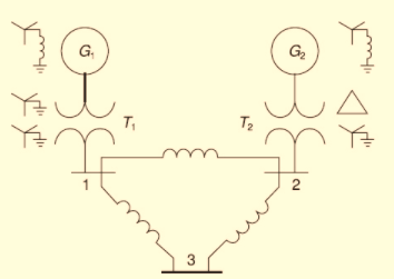
The neutral of each generator is grounded through a current-limiting reactor of 0.08333 per unit on a 100-MVA base. All transformer neutrals are solidly grounded. The generators are operating no-load at their rated voltages and rated frequency with their ENIFs in phase. Determine the fault current for a balanced three-phase fault at bus 3 through a fault impedance

Trending nowThis is a popular solution!

Chapter 9 Solutions
Power System Analysis and Design (MindTap Course List)


- Three zones of a single-phase circuit are identified in Figure. The zones are connected bytransformers T1 and T2, whose ratings are also shown.Using base values of 30 kVA and 240 volts in zone 1:a. draw the per-unit circuit and determine the per-unit impedances and the per-unitsource voltage.b. calculate the load current both in per-unit and in amperes. Transformer windingresistances and shunt admittance branches are neglected.arrow_forward8. A 1000-kV and a 500-kVA, 1-phase transformers are connected to the same bus-bars on the primary side. The secondary e.m.fs at no-load are 500 and 510 V respectively. The impedance voltage of the first transformer is 3.4% and of the second 5%. What cross-current will pass between them when the secondaries are connected together in parallel? Assuming that the ratio of resistance to reactance is the same in each, what currents will flow in the windings of the two transformers when supplying a total load of 1200 kVA. [(a) 290 A (b) 1577 and 900 A]arrow_forwardwhat is the definition of zero sequence impedance in a transformers? And what is the benefit of this check in transformers?arrow_forward
- 6. A 3 phase fault occurs at point F as shown in figure. Determine the critical clearing anglefor the system. The generator is delivering 1.0 p.u power under prefault conditioarrow_forward1.a. Separate voltage-regulating units provide voltage-ratio control under load byA. causing different impedance drops in each phase.B. combining voltages from different phases.C. having series transformers in phase with the line-to-neutral voltage.D. exciting transformers having their primaries delta-connected. 1.b. A reactor is sometimes used with an autotransformer toA. limit short-circuit current.B. increase the full-load current.C. provide increased internal impedance.D. decrease the voltage ratio.arrow_forwardUDng a ITIe Core in high frequency transformers. c- Discuss, different applications of iron cores of different hysteresis loops. d- Explain the effect of Inrush current on power transformers.arrow_forward
- Three single-phase two-winding transformers, each rated 3kVA,220/110volts,60Hz, with a 0.10 per-unit leakage reactance, are connected as a three-phase extended autotransformer bank, as shown in Figure 3.36(c). The low-voltage winding has a 110 volt rating. (a) Draw the positive-sequence phasor diagram and show that the high-voltage winding has a 479.5 volt rating. (b) A three-phase load connected to the low-voltage terminals absorbs 6 kW at 110 volts and at 0.8 power factor lagging. Draw the per-unit impedance diagram and calculate the voltage and current at the high-voltage terminals. Assume positive-sequence operation.arrow_forwardThree single-phase, two-winding transformers, each rated 450MVA,20kV/288.7kV, with leakage reactance Xeq=0.10perunit, are connected to form a three-phase bank. The high-voltage windings are connected in Y with a solidly grounded neutral. Draw the per-unit equivalent circuit if the low-voltage windings are connected (a) in with American standard phase shift or (b) in Y with an open neutral. Use the transformer ratings as base quantities. Winding resistances and exciting current are neglected.arrow_forwardThree single-phase two-winding transformers, each rated 25MVA,54.2/5.42kV, are connected to form a three-phase Y- bank with a balanced Y-connected resistive load of 0.6 per phase on the low-voltage side. By choosing a base of 75 MVA (three phase) and 94 kV (line-to-line) for the high-voltage side of the transformer bank, specify the base quantities for the low-voltage side. Determine the per-unit resistance of the load on the base for the low-voltage side. Then determine the load resistance RL in ohms referred to the high-voltage side and the per-unit value of this load resistance on the chosen base.arrow_forward
- What is the maximum volt-ampere rating of transformers supplying Class 2 systems? ___________arrow_forwardConsider a bank of this single-phase two-winding transformers whose high-voltage terminals are connected to a three-phase, 13.8-kV feeder. The low-voltage terminals are connected to a three-phase substation load rated 2.0 MVA and 2.5 kV. Determine the required voltage, current, and MVA ratings of both windings of each transformer, when the high-voltage/low- voltage windings are connected (a) Y-, (b) -Y, (c) Y-Y, and (d) -.arrow_forwardConsider the oneline diagram shown in Figure 3.40. The three-phase transformer bank is made up of three identical single-phase transformers, each specified by X1=0.24 (on the low-voltage side), negligible resistance and magnetizing current, and turns ratio =N2/N1=10. The transformer bank is delivering 100 MW at 0.8 p.f. lagging to a substation bus whose voltage is 230 kV. (a) Determine the primary current magnitude, primary voltage (line-to-line) magnitude, and the three-phase complex power supplied by the generator. Choose the line-to-neutral voltage at the bus, Va as the reference Account for the phase shift, and assume positive-sequence operation. (b) Find the phase shift between the primary and secondary voltages.arrow_forward
 Power System Analysis and Design (MindTap Course ...Electrical EngineeringISBN:9781305632134Author:J. Duncan Glover, Thomas Overbye, Mulukutla S. SarmaPublisher:Cengage Learning
 EBK ELECTRICAL WIRING RESIDENTIALElectrical EngineeringISBN:9781337516549Author:SimmonsPublisher:CENGAGE LEARNING - CONSIGNMENT