
Videos
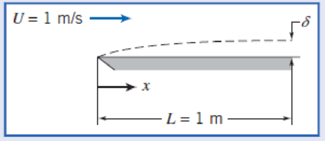
Assume the flow conditions given in Example 9.3. Plot δ, δ*, and τw versus x/L for the plate.
Example 9.3 TURBULENT BOUNDARY LAYER ON A FLAT PLATE: APPROXIMATE SOLUTION USING
Water flows at U = 1 m/s past a flat plate with L = 1 min the flow direction. The boundary layer is tripped so it becomes turbulent at the leading edge. Evaluate the disturbance thickness, δ, displacement thickness, δ*, and wall shear stress, τw, at x = L. Compare with laminar flow maintained to the same position. Assume a
Given: Flat-plate boundary-layer flow; turbulent flow from the leading edge. Assume
Find: (a) Disturbance thickness, δL.
(b) Displacement thickness,
(c) Wall shear stress, τw(L).
(d) Comparison with results for laminar flow from the leading edge.
Solution: Apply results from the momentum integral equation.
Governing equations:
At x = L, with ν = 1.00 × 10⁻⁶ m2/s for water (T = 20°C),
From Eq. 9.26,
Using Eq. 9.1, with u/U = (y/δ)1/7 = η1/7, we obtain
From Eq. 9.27,
For laminar flow, use Blasius solution values. From Eq. 9.13 (on the web),
From Example W9.1, δ*/δ = 0.344, so
Want to see the full answer?
Check out a sample textbook solution
Chapter 9 Solutions
Fox and McDonald's Introduction to Fluid Mechanics
Additional Engineering Textbook Solutions
DeGarmo's Materials and Processes in Manufacturing
Fundamentals Of Thermodynamics
Manufacturing Engineering & Technology
Automotive Technology: Principles, Diagnosis, And Service (6th Edition) (halderman Automotive Series)
Engineering Mechanics: Statics & Dynamics (14th Edition)
Automotive Technology: Principles, Diagnosis, and Service (5th Edition)


- Air flows through the test section of a small wind tunnel at speed V = 7.5 ft/s. The temperature of the air is 80°F, and the length of the wind tunnel test section is 1.5 ft. Assume that the boundary layer thickness is negligible prior to the start of the test section. Is the boundary layer along the test section wall laminar or turbulent or transitional?From above problem.assume the flow remains laminar, and estimate the boundary layer thickness, the displacement thickness, and the momentum thickness of the boundary layer at the end of the test section. Give your answers in inches, compare the three results, and discuss. .arrow_forwardAir flows over a flat plate with a velocity u = 13 m/s and temperature T. = 25 °C. The plate surface area and temperature are A = 2 x 2 m and T, =125 °C, respectively. a- Determine the critical length X (length of the laminar region). b- Determine the rate of heat transfer in the laminar region. %3D C- Determine the total rate of heat transfer from the entire plate (mixed boundary layer). Use the following properties of air H = 2.08 x 10 N.s/m, p = 0.887 kg/m, k = 0.0325 W/m.K, Pr = 0.705 %3D rinar @111arrow_forwardHelp me pleasearrow_forward
- The figure shows a multiple duct made up of seven 2cm diameter tubes grouped in a hexagonal mesh, within a 6cm diameter tube. Estimate the pressure drop per unit length if 150m^3/h of air at 20°C and 1 atm of pressure flow through the duct.arrow_forward1) For a parallel laminar flow over flat plates, the friction coefficient depends only on the Reynolds number. In the fully rough turbulent regime, the friction coefficient only relates to the surface roughness. True or False 2) a car is placed in a large wind tunnel for a full scale test. The upstream velocity is determined to be 20 m/s. The frontal area of the car is 15 m2. If the force acting on the car in the flow direction is measured to be 1000 N, what is the drag coefficient of this car? Assume the air density = 1.14 kg/m3. a) 0.15 b) 0.29 c) 0.34 d) 0.34 Ns/m 3) Drag force include friction drag and pressure drag. Friction drag increase with the increment of viscosity of the fluid. True or Falsearrow_forwardAir at 20°C forms a boundary layer near a solid wall, in which the velocity profile, U = Umax sin TY 20 as shown below. 7 mm V max = 9 m/s Peak Sine wave The boundary layer thickness is 7mm, viscosity is 1.81 x 10⁻⁵Ns/m² and the peak velocity is 9m/s. Compute the shear stress in the boundary layer at y = 3.5mm.arrow_forward
- 1. Consider a new wind tunnel to test and utilise the effects of boundary layer conditions in order to maintain the velocity of a fluid. Laminar airflow enters a square duct design through a 0.25m² opening, as is shown in Figure 1. Because the boundary layer displacement thickness increases in the direction of flow, it is necessary to increase the cross-sectional size of the duct if a constant U=1 m/s velocity to be maintained outside the boundary layer. Assume standard air temperature in the calculation. U = 1 m/s 0.25 m2 d(x) 1 m/s Figure 1 a) Determine the expression of the duct size, d, in consideration to maintain the velocity outside the boundary layer. b) Plot a graph of the duct size, d, as a function of x for 0arrow_forwardA helicopter during a test has its four blades turning at 89 rpm with the blades oriented parallel to the plane of rotation, where each blade is 3.5 m long, and the average width is 200 mm, Transition is at a Reynolds number on 10^ 6. Find out what power is needed to maintain this rotation of the four blades? Consider only skin drag. Take air density = 1.225kg/m^3 and air viscosity = 1.78 X 10E-5 Pa.s %3Darrow_forwardFlow straighteners consist of arrays of narrow ducts placed in a flow to remove swirl and other transverse (secondary) velocities. One element can be idealised as a square box with thin sides as shown below. Calculate the pressure drop across a box with L=22 cm and a= 2.7 cm, if air with free-stream velocity of Uo = 11 m/s flows though the straightener. Use laminar flat-plate theory and take u = 1.85 x 10⁻⁵ Pa.s and p = 1.177kg/m³ . %3D %3D a Uo Figure 1: Flow across straighteners.arrow_forwardFrom the laminar boundary layer the velocity distributions given below, find the momentum thickness θ, boundary layer thickness δ, wall shear stress τw, skin friction coefficient Cf , and displacement thickness δ*1. A linear profile, u(x, y) = a + by 2. von K ́arm ́an’s second-order, parabolic profile,u(x, y) = a + by + cy2 3. A third-order, cubic function,u(x, y) = a + by + cy2+ dy3 4. Pohlhausen’s fourth-order, quartic profile,u(x, y) = a + by + cy2+ dy3+ ey4 5. A sinusoidal profile,u = U sin (π/2*y/δ)arrow_forwardQ1: Find the boundary layer thickness (6) equation, the shear stress (to) and the coefficient of drag (C₁) if the velocity distribution in the laminar boundary layer over the face of a spillway was observed to be: u 7- (C)-()*+C)*. U Then calculate the boundary layer thickness and drag force if the air flows over a sharp edged flat plate 0.25m long and 0.5m wide at a velocity 1 m/s, take the air density 1.23 kg/m³ and the kinematic viscosity is 1.46*10-5 m/s².arrow_forwardIn the flow of air at 20°C and 1 atm past a flat plate inFig. , the wall shear is to be determined at position x bya floating element (a small area connected to a strain-gageforce measurement). At x = 2 m, the element indicates ashear stress of 2.1 Pa. Assuming turbulent flow from the leadingedge, estimate (a) the stream velocity U, (b) the boundarylayer thickness δ at the element, and (c) the boundary layervelocity u, in m/s, at 5 mm above the element.arrow_forwardarrow_back_iosSEE MORE QUESTIONSarrow_forward_ios
 Elements Of ElectromagneticsMechanical EngineeringISBN:9780190698614Author:Sadiku, Matthew N. O.Publisher:Oxford University Press
 Mechanics of Materials (10th Edition)Mechanical EngineeringISBN:9780134319650Author:Russell C. HibbelerPublisher:PEARSON
 Thermodynamics: An Engineering ApproachMechanical EngineeringISBN:9781259822674Author:Yunus A. Cengel Dr., Michael A. BolesPublisher:McGraw-Hill Education
 Control Systems EngineeringMechanical EngineeringISBN:9781118170519Author:Norman S. NisePublisher:WILEY
 Mechanics of Materials (MindTap Course List)Mechanical EngineeringISBN:9781337093347Author:Barry J. Goodno, James M. GerePublisher:Cengage Learning
 Engineering Mechanics: StaticsMechanical EngineeringISBN:9781118807330Author:James L. Meriam, L. G. Kraige, J. N. BoltonPublisher:WILEY